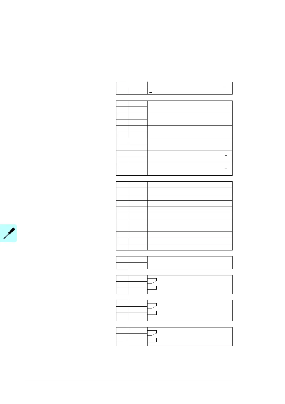
RMIO
X20
1 VREF- Reference voltage -10 V DC, 1 kohm <
R
L
< 10 kohm
2 AGND
X21
1 VREF+ Reference voltage 10 V DC, 1 kohm <
R
L
<
10 kohm
2AGND
3 AI1+ DC current measurement -10 … 10 V
4AI1-
5 AI2+ Grounding current measurement.
4…20 mA, R
in
= 100 ohm
4)
6AI2-
7 AI3+ Solar generator DC voltage measurement.
0(4)…20 mA, R
in
= 100 ohm
8AI3-
9 AO1+ By default, not in use. 0(4)…20 mA, R
L
<
700 ohm
10 AO1-
11 AO2+ By default, not in use. 0(4)…20 mA, R
L
<
700 ohm
12 AO2-
X22
1DI1 Reset
2 DI2 By default, not in use.
1)
3 DI3 AC and DC overvoltage protection
4 DI4 DC cable overcurrent protection
5 DI5 By default, not in use
5)
6 DI6 Status of the emergency stop circuit
7 +24VD +24 V DC max. 100 mA
8+24VD
9 DGND1 Digital ground
10 DGND2 Digital ground
11 DIIL DC grounding acknowledgement
4)
X23
1 +24V Auxiliary voltage output and input, non-
isolated, 24 V DC 250 mA
2)
2GND
X25
1 RO1 Relay output 1: By default, not in
use. With option +Q951 reserved.
3)
2RO1
3RO1
X26
1 RO2 Relay output 2: Fault indication
6)
1 = No fault
0 = Fault
2RO2
3RO2
X27
1 RO3 Relay output 3: Grounding switch
control
4)
2RO3
3RO3
Terminal block size:
cables 0.3 to 3.3 mm
2
(22 to 12 AWG)
Tightening torque:
0.2 to 0.4 N·m
(0.2 to 0.3 lbf·ft)
1) Can be configured for Start/Stop or
other use with parameter settings.
2) Total maximum current shared
between this output and the optional
modules installed on the board.
3) Can be configured with parameter
settings for resetting the emergency
stop circuit with the emergency stop
reset button on the cabinet door
(option +Q951 in PVS800-57-0100kW,
-0250kW and -0315kW units).
4) Used only with options +F282 and
+F283.
5) Transformer trip (MWS)
6) Can be configured with parameter
66.03 DO2.

 Loading...


