52 Operation principle and hardware description
Connections and interfaces overview
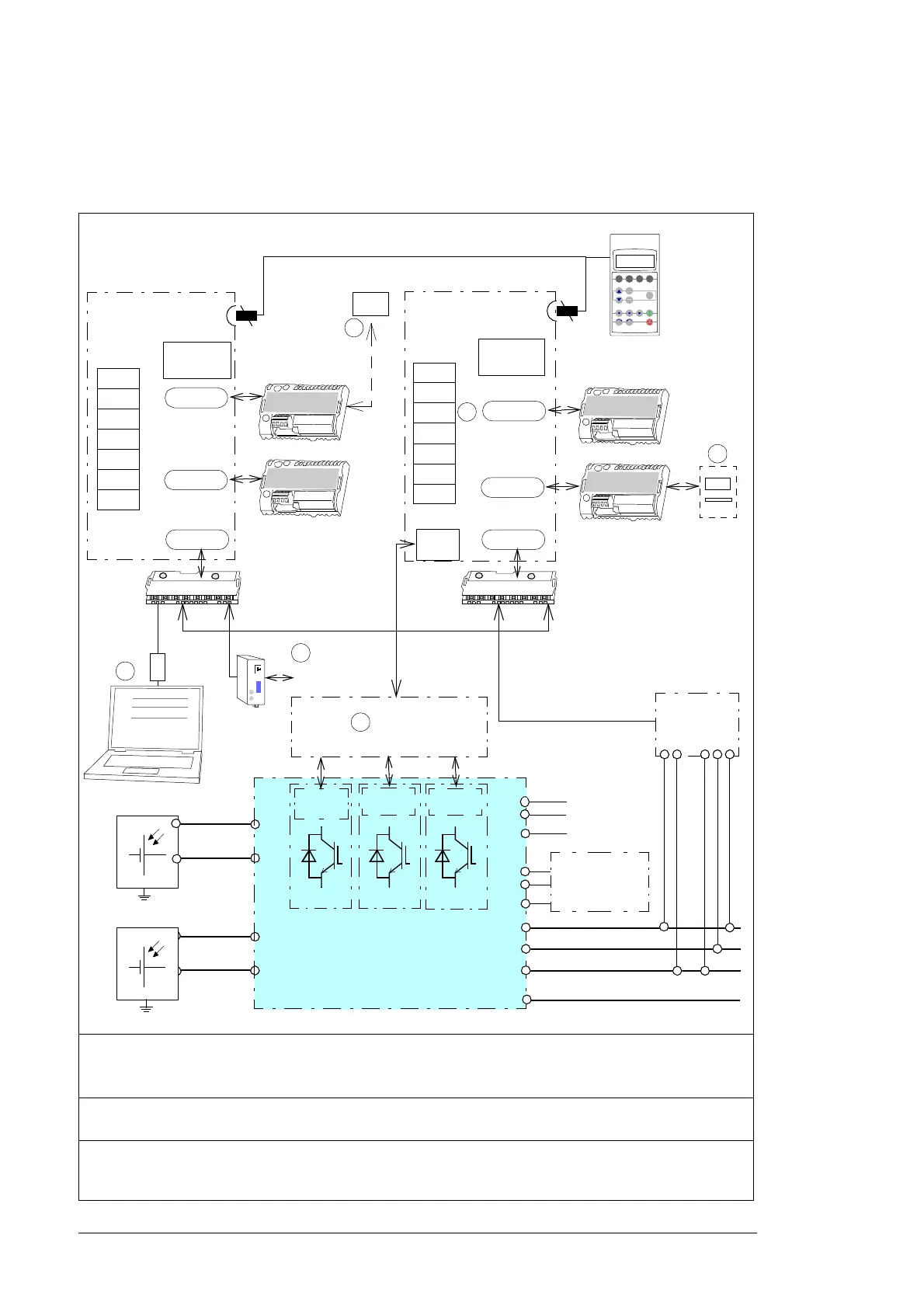
The diagram below shows the power connections and control interfaces of the PVS800-57
inverters.
1)
Monitoring and/or controlling of the inverter;
2)
Grid monitoring relay (option +Q969, +Q974, +Q975 or
+Q980);
3)
See page 96;
4)
Ground fault monitoring (option +Q954, +Q976 or +Q981)
5)
Remote monitoring (default connection). For ring topology, see the firmware manual for the required
parameter settings.
6)
APBU branching unit and connection to AINT boards through APBU only in frames 2 × R8i and 3 × R8i. In
frames 1 × R7i and 1 × R8i, the fiber optic cables from A41 are connected directly to AINT. 2 × R8i uses
channels CH1 and CH2 for the connection.
...
L+
L-
L+
L-
SLOT 1
DDCS
X20
X21
X22
X23
X25
X26
X27
SLOT 2
R
D
C
O
+24 V DC
ExtPower
RDCU
Control
panel
R
x
x
x
SLOT 1
SLOT 2
R
x
x
x
+24 V DC
ExtPower
PLC
DDCS
R
D
C
O
X20
X21
X22
X23
X25
X26
X27
RDCU
Control
panel
R
x
x
x
R
D
I
O
NETA
PC
Internet
L1
L2
L3
PE
230 V AC
Q10
2
4
PE
L
N
PE
(A41)
(A43)
CH0CH2CH3
DriveWindow
AINT
CH0
AINT
APBU
CH1
CH2
Inverter
TXD
RXD
CNTL 1
2
5
3
6
1
I0
CDP312R
NAMU
2×I 3×U
CH2
X21
1
2
3
Junction box
4
AINT
CH3

 Loading...


