42 Operation principle and hardware description
Positive or negative pole grounding (options +F282 and
+F283)
The positive and negative pole grounding options can be used when solar modules require
grounding of inverter DC poles. The grounding of the poles complies with standard
IEC 62109-2. One DC line needs to be grounded for certain thin-film photovoltaic module
types and if required by country-specific regulations.
The grounding is always connected when auxiliary power is connected, except when the
automatic photovoltaic generator insulation check is done before the inverter starts.
The grounding wire is protected by a fuse on the PGND-02 board. Due to personnel
protection reasons, the grounding is disconnected when sudden level changes are
monitored from the grounding wire current.
The grounding resistance can be adjusted by the user. For instructions, see page 101.
Reduced run operation in case of a hardware failure
If an inverter module or an LCL filter is out of order, it is possible to continue running the
inverter with reduced output current. In this case the inverter controls only modules which
are unbroken. Inverter output current is reduced in relation to the removed modules. For
example, if one inverter module is broken in PVS800-57-1000kW-C, the inverter output
current is reduced to 66.7% of the nominal current. Reduced run is not possible with
inverters that have only one inverter module.
To operate the PVS800 with reduced run, you must remove the charging circuit fuses
specified in the tables below. However, you do not have to remove the broken inverter
module or LCL filter. This is possible because broken parts can be isolated with AC and
DC contactors inside the PVS800 cabinet. For removing the broken component, obey the
instructions in chapter Maintenance.
Inverter modules are divided into two control groups, which can be enabled or disabled
according to the need. If a module group is disabled, the inverter modules which are part
of that group are not used. The following tables list the possible control combinations in the
reduced run operation.
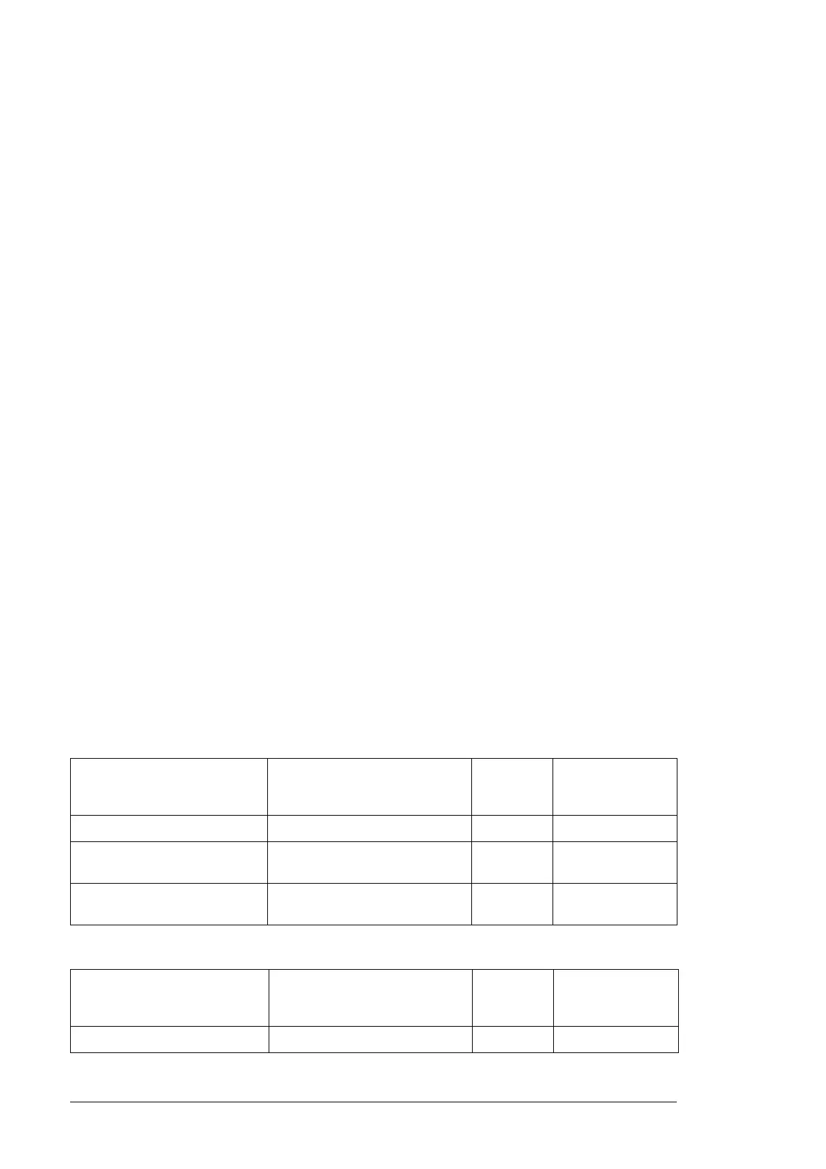
PVS800-57-500kW-A and PVS800-57-630kW-B:
PVS800-57-875kW-B and PVS800-57-1000kW-C:
Inverter control unit parameter
16.05 USED MODULES
Description Reduced
output
current
Charging circuit
fuses to be
removed
GROUP 1 Left inverter module (U1) is used. 50% F20.3-4
GROUP 2 Right inverter module (U2) is
used.
50% F20.1-2
GROUPS 1 and 2 (default) Left (U1) and right (U2) inverter
modules are used.
100% None
Inverter control unit parameter
16.05 USED MODULES
Description Reduced
output
current
Charging circuit
fuses to be
removed
GROUP 1 Left inverter module (U1) is used. 33.3% F20.3-6

 Loading...


