78 Planning the electrical installation
Signals in separate cables
Run analog and digital signals in separate, shielded cables.
Never mix 24 V DC and 115/230 V AC signals in the same cable.
Signals allowed to be run in the same cable
Relay-controlled signals, providing their voltage does not exceed 48 V, can be run in the
same cables as digital input signals. It is recommended that the relay-controlled signals be
run as twisted pairs.
Relay cable type
The cable type with braided metallic screen (eg, ÖLFLEX by LAPPKABEL, Germany) has
been tested and approved by ABB.
Installation sites above 2000 metres (6560 feet)
WARNING! Protect against direct contact when installing, operating and servicing
the RMIO board wiring and optional modules attached to the board. The
Protective Extra Low Voltage (PELV) requirements stated in EN 50178 are not
fulfilled at altitudes above 2000 m (6560 ft).
Routing the cables
It is recommended that the input DC power cable, output AC power cable and control
cables be installed on separate trays.
Where control cables must cross power cables ensure they are arranged at an angle as
near to 90 degrees as possible. Do not run extra cables through the inverter.
The cable trays must have good electrical bonding to each other and to the grounding
electrodes. Aluminium tray systems can be used to improve local equalizing of potential.
If four conductor AC cabling is used, place the three output phase cables symmetrically
and close to each other. Asymmetrical installation may induce current to grounding cables
and metal structures.
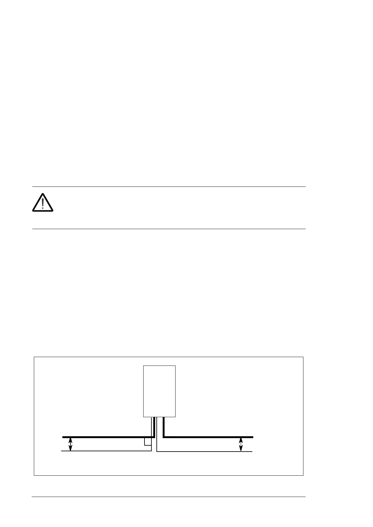
A diagram of the cable routing is shown below.
90 °
DC input cableAC output power cable
Control cables
min 500 mm (19.7 in.)
Inverter
min 500 mm (19.7 in.)

 Loading...


