en05000214_ansi.vsd
REFx
I3P
I3PW1CT1
I3PW1CT2
C
B
A
INd>
{
{
52
52
52 52
52
52
ANSI05000214 V1 EN
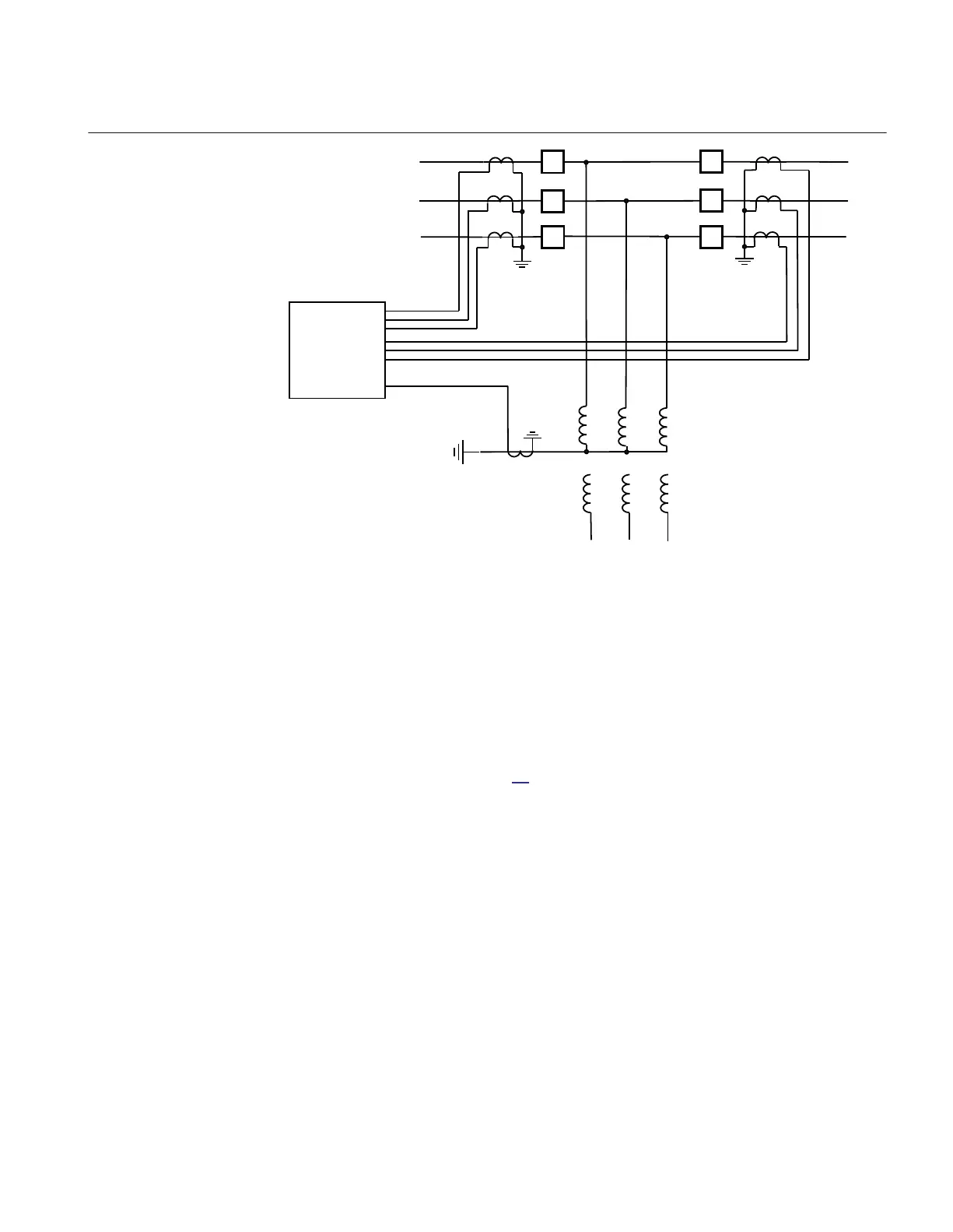
Figure 34: Connection of Restricted earth fault, low impedance function REFPDIF
(87N) in multi-breaker arrangements
CT grounding direction
To make the restricted earth-fault protection REFPDIF (87N)operate correctly, the
main CTs are always supposed to be wye connected. The main CT's neutral (star)
formation can be positioned in either way, ToObject or FromObject. However,
internally REFPDIF (87N) always uses reference directions towards the protected
transformers, as shown in figure
34. Thus the IED always measures the primary
currents on all sides and in the neutral of the power transformer with the same
reference direction towards the power transformer windings.
The grounding can, therefore, be freely selected for each of the involved current
transformers.
3.5.2.2 Setting guidelines
Setting and configuration
Recommendation for analog inputs
I3P: Neutral point current ( All analog inputs connected as 3Ph groups in ACT).
I3PW1CT1: Phase currents for winding 1 first current transformer set.
1MRK504116-UUS C Section 3
IED application
131
Application manual

 Loading...


