Table 102: SDEPSDE (67N) Non group settings (basic)
Name Values (Range) Unit Step Default Description
IBase 1 - 99999 A 1 100 Base Current, in A
VBase 0.05 - 2000.00 kV 0.05 63.50 Base Voltage, in kV Phase to Neutral
SBase 0.05 -
200000000.00
kVA 0.05 6350.00 Base Power, in kVA. IBase*Ubase
Table 103: SDEPSDE (67N) Non group settings (advanced)
Name Values (Range) Unit Step Default Description
RotResV 0 deg
180 deg
- - 180 deg Setting for rotating polarizing quantity if
necessary
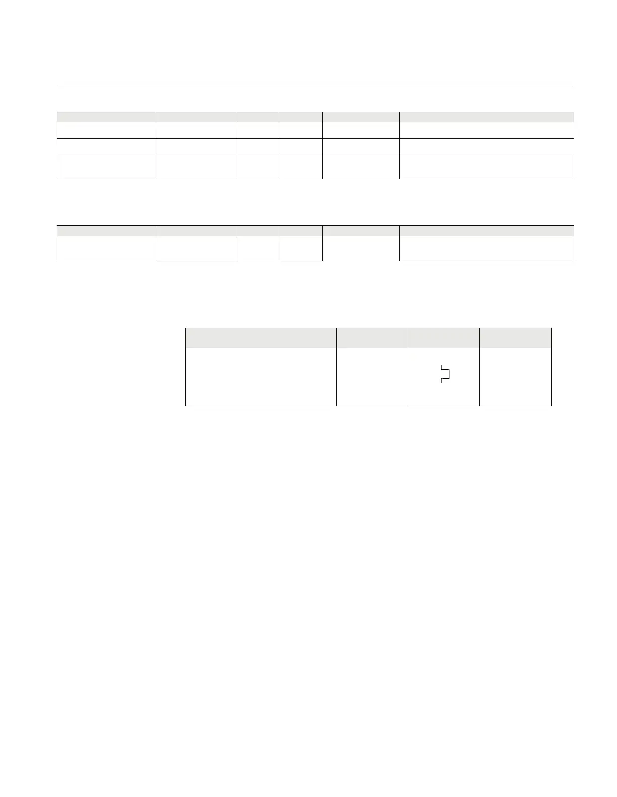
3.7.7 Thermal overload protection, two time constants TRPTTR (49)
Function description IEC 61850
identification
IEC 60617
identification
ANSI/IEEE C37.2
device number
Thermal overload protection, two time
constants
TRPTTR
SYMBOL-A V1 EN
49
3.7.7.1 Application
Transformers in the power system are designed for a certain maximum load current
(power) level. If the current exceeds this level the losses will be higher than expected.
As a consequence the temperature of the transformer will increase. If the temperature
of the transformer reaches too high values the equipment might be damaged:
• The insulation within the transformer will have forced ageing. As a consequence
of this, the risk of internal phase-to-phase or phase-to-ground faults will increase.
• There might be hot spots within the transformer, which will degrade the paper
insulation. It might also cause bubbling in the transformer oil.
In stressed situations in the power system it can be required to overload transformers
for a limited time. This should be done without the above mentioned risks. The thermal
overload protection provides information and makes temporary overloading of
transformers possible.
The permissible load level of a power transformer is highly dependent on the cooling
system of the transformer. There are two main principles:
1MRK504116-UUS C Section 3
IED application
465
Application manual

 Loading...


