3.13.2.1 Application
Fault current reversal logic
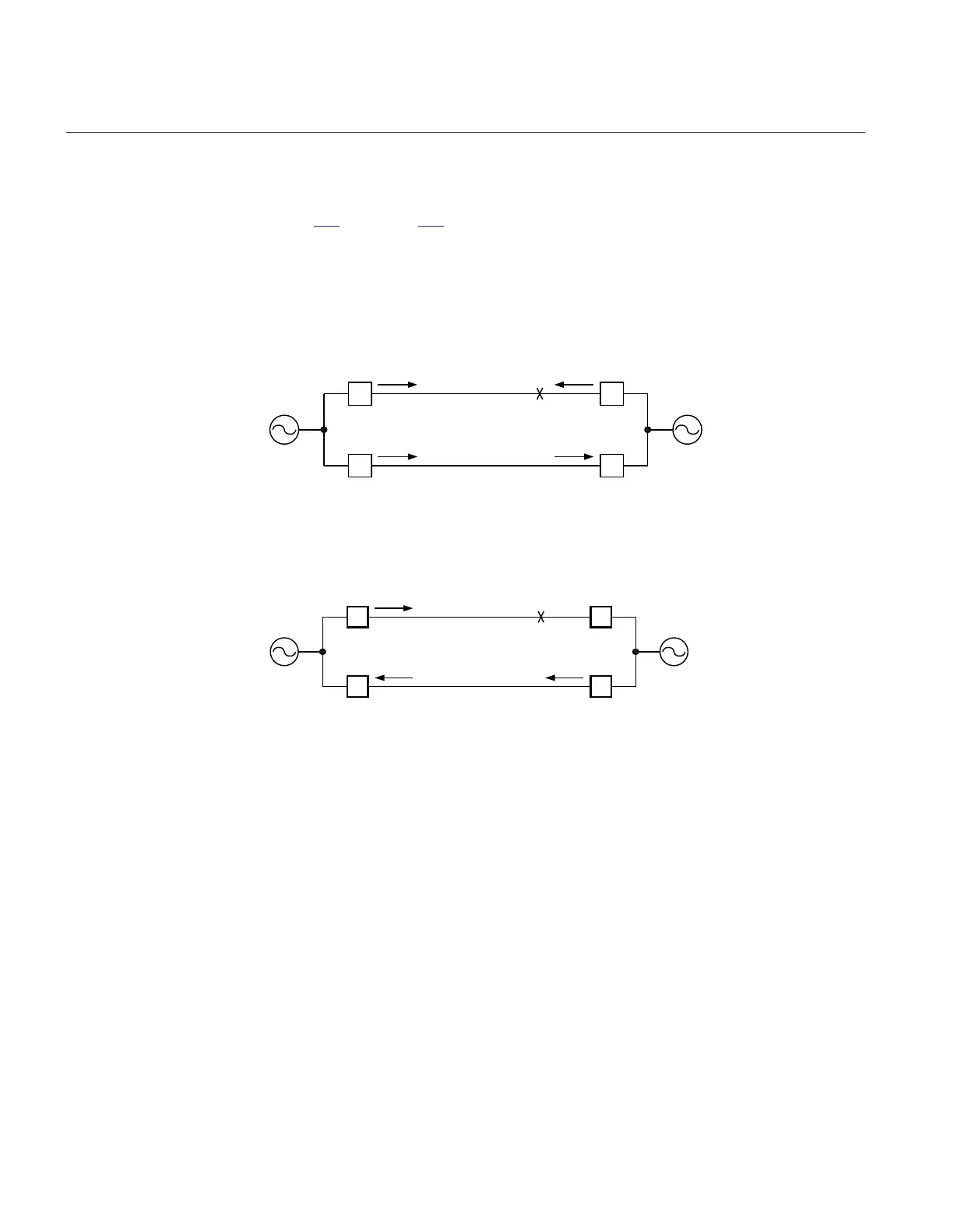
Figure 296 and figure 297 show a typical system condition, which can result in a fault
current reversal.
Note that the fault current is reversed in line L2 after the breaker opening.
This can cause an unselective trip on line L2 if the current reversal logic does not block
the permissive overreaching scheme in the IED at B:2.
en99000043_ansi.vsd
Strong
source
LINE 1
LINE 2
A:1
A:2
B:1
B:2
A B
Weak
source
FAULT
CLOSED
CLOSED
CLOSED
CLOSED
ANSI99000043 V1 EN
Figure 296: Initial condition
en99000044_ansi.vsd
Strong
source
LINE 1
LINE 2
A:1
A:2
B:1
B:2
A B
Weak
source
CLOSED
CLOSED
OPEN
CLOSED
FAULT
ANSI99000044 V1 EN
Figure 297: Current distribution after the breaker at B:1 is opened
When breaker on the parallel line operates, the fault current on the non faulty line is
reversed. The IED at B:2 recognizes now the fault in forward direction. Together with
the remaining received signal it will trip the breaker in B:2. To ensure that this does not
occur, the permissive overreaching function needs to be blocked by IRVL, until the
received signal is reset.
The IED at remote end, where the forward direction element was initially activated,
must reset before the send signal is initiated from B:2. The delayed reset of output
signal IRVL also ensures the send signal from IED B:2 is held back until the forward
direction element is reset in IED A:2.
Section 3 1MRK504116-UUS C
IED application
732
Application manual

 Loading...


