Setting of direction for offset mho
If offset mho has been selected, one can select if the offset mho shall be Non-
Directional, Forward or Reverse by setting the parameter OfffsetMhoDir.
When forward or reverse operation is selected, then the operation characteristic will be
cut off by the directional lines used for the mho characteristic. The setting is by default
set to Non-Directional.
Setting of timers for distance protection zones
The required time delays for different distance protection zones are independent of
each other. Distance protection zone 1 can also have a time delay, if so required for
selectivity reasons. One can set the time delays for all zones in a range of 0 to 60
seconds. The tripping function of each particular zone can be inhibited by setting the
corresponding Operation parameter to OffDisable-Zone.
Different time delays are possible for the phase-to-groundtLG and for the phase-to-
phase tPP measuring loops in each distance protection zone separately, to further
increase the total flexibility of a distance protection.
In the case of evolving faults or momentary current transformer saturation conditions,
the pick up of the zones may get delayed. Zone timer logic improves the operating time
in such conditions. The zone timer logic can be set using the parameter ZnTimerSel.
The triggering signal of phase-to-ground and phase-to-phase timers can be selected
using ZnTimerSel.
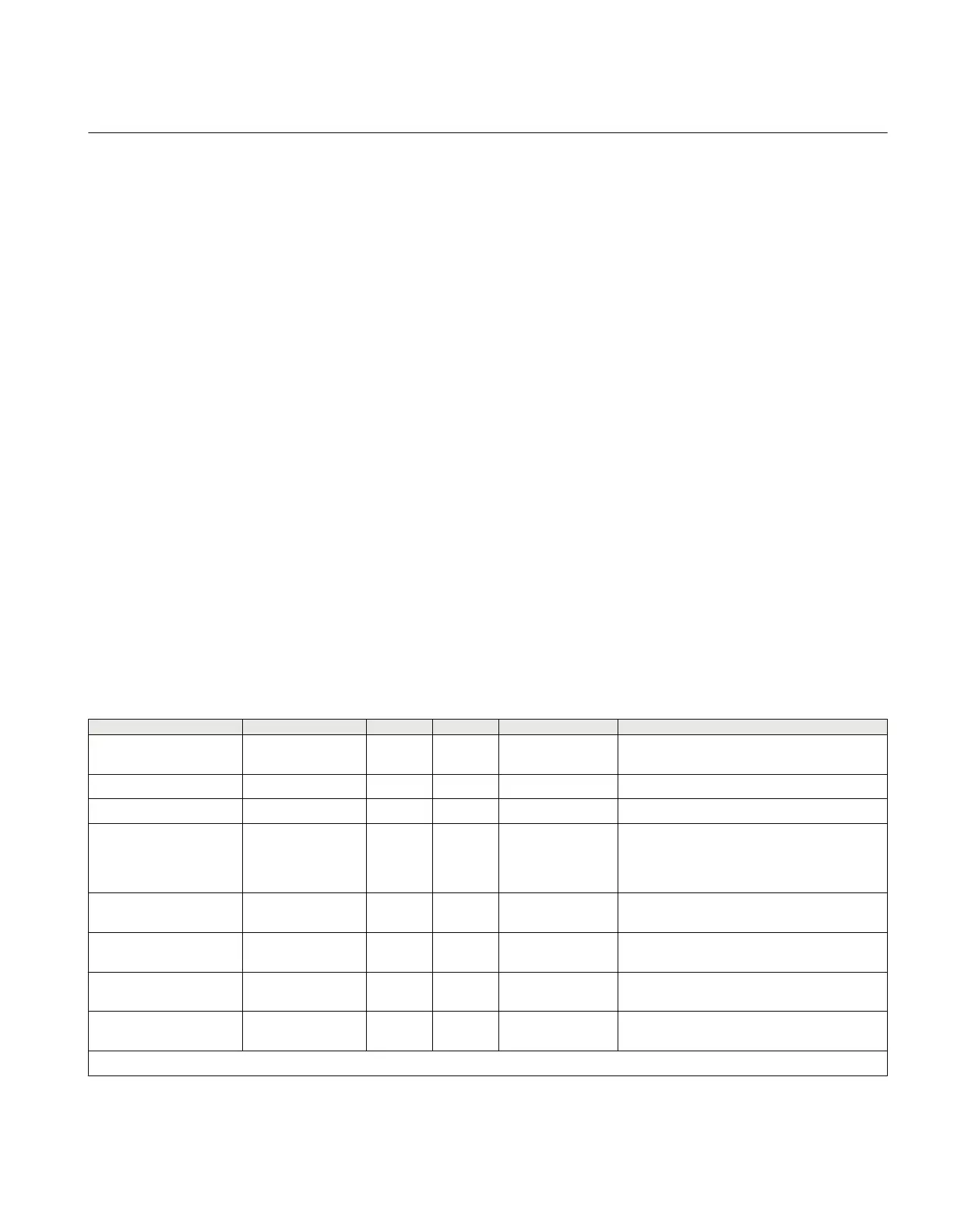
3.6.4.3 Setting parameters
Table 60: ZMHPDIS (21) Group settings (basic)
Name
Values (Range) Unit Step Default Description
Operation Disabled
Enabled
- - Enabled Operation Enable/Disable
IBase 1 - 99999 A 1 3000 Base current
VBase 0.05 - 2000.00 kV 0.05 400.00 Base voltage
DirMode Disabled
Offset
Forward
Reverse
- - Forward Direction mode
LoadEncMode Disabled
Enabled
- - Disabled Load encroachment mode Off/On
ReachMode Overreach
Underreach
- - Overreach Reach mode Over/Underreach
OpModePG Disabled
Enabled
- - Enabled Operation mode Disable/Enable of Phase-
Ground loops
ZPG 0.005 - 3000.000 ohm/p 0.001 30.000 Positive sequence impedance setting for
Phase-Ground loop
Table continues on next page
1MRK504116-UUS C Section 3
IED application
281
Application manual

 Loading...


