3.6.6.3 Setting parameters
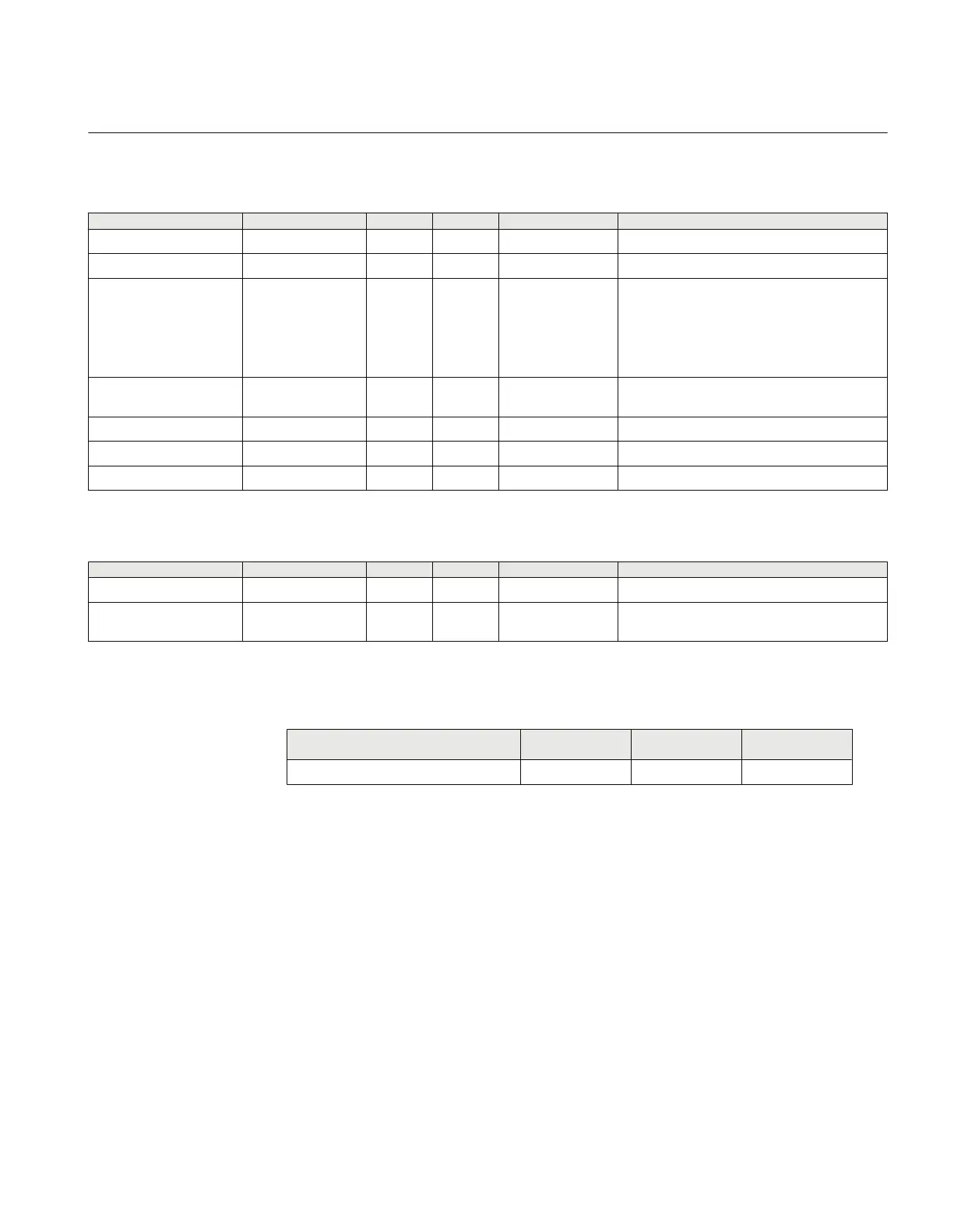
Table 66: ZDARDIR Group settings (basic)
Name Values (Range) Unit Step Default Description
IBase 1 - 99999 A 1 3000 Base setting for current values
VBase 0.05 - 2000.00 kV 0.05 400.00 Base setting for voltage level in kV
PolMode -3U0
-V2
IPol
Dual
-3U0Comp
-V2comp
- - -3U0 Polarization quantity for opt dir function for P-
G faults
AngleRCA -90 - 90 Deg 1 75 Characteristic relay angle (= MTA or base
angle)
IPickup 1 - 200 %IB 1 5 Minimum operation current in % of IBase
VPolPU 1 - 100 %VB 1 1 Minimum polarizing voltage in % of VBase
IPolPU 5 - 100 %IB 1 10 Minimum polarizing current in % of IBase
Table 67: ZDARDIR Group settings (advanced)
Name Values (Range) Unit Step Default Description
AngleOp 90 - 180 Deg 1 160 Operation sector angle
Kmag 0.50 - 3000.00 ohm 0.01 40.00 Boost-factor in -V0comp and -V2comp
polarization
3.6.7 Mho impedance supervision logic ZSMGAPC
Function description
IEC 61850
identification
IEC 60617
identification
ANSI/IEEE C37.2
device number
Mho Impedance supervision logic ZSMGAPC - -
3.6.7.1 Application
The Mho impedance supervision logic (ZSMGAPC) includes features for fault
inception detection and high SIR detection. It also includes the functionality for loss of
potential logic as well as for the pilot channel blocking scheme.
One part of ZSMGAPC function identifies a loss of phase potential that is the result of
a long term (steady state) condition such as a blown fuse or an open voltage
transformer winding or connection. This will block all trips by the distance protection
since they are based on voltage measurement.
1MRK504116-UUS C Section 3
IED application
309
Application manual

 Loading...


