3.12.3.3 Interlocking for bus-coupler bay ABC_BC (3)
Application
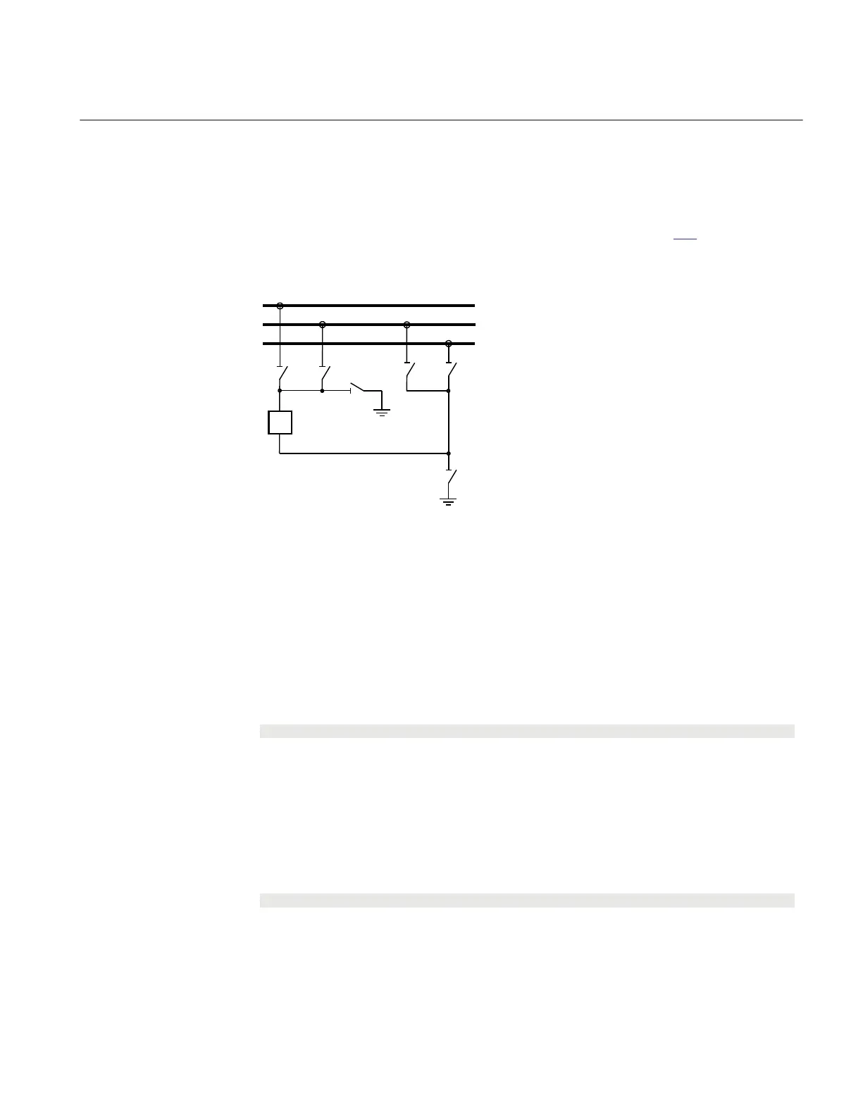
The interlocking for bus-coupler bay (ABC_BC, 3) function is used for a bus-coupler
bay connected to a double busbar arrangement according to figure
242. The function
can also be used for a single busbar arrangement with transfer busbar or double busbar
arrangement without transfer busbar.
189 289
189G
WA1 (A)
WA2 (B)
WA7 (C)
789
2089
289G
en04000514_ansi.vsd
152
ANSI04000514 V1 EN
Figure 242: Switchyard layout ABC_BC (3)
Configuration
The signals from the other bays connected to the bus-coupler module ABC_BC are
described below.
Signals from all feeders
To derive the signals:
Signal
BBTR_OP No busbar transfer is in progress concerning this bus-coupler.
VP_BBTR The switch status is valid for all apparatuses involved in the busbar transfer.
EXDU_12 No transmission error from any bay connected to the WA1/WA2 busbars.
These signals from each line bay (ABC_LINE), each transformer bay (AB_TRAFO),
and bus-coupler bay (ABC_BC), except the own bus-coupler bay are needed:
Signal
Q1289OPTR 189 or 289 or both are open.
VP1289TR The switch status of 189 and 289 are valid.
EXDU_12 No transmission error from the bay that contains the above information.
1MRK504116-UUS C Section 3
IED application
623
Application manual

 Loading...


