WA1 (A)
WA2 (B)
189
189G
289G
989G
6189
989
289
489G
589G
389G
6289
DB_BUS_B
DB_LINE
DB_BUS_A
en04000518_ansi.vsd
252
152
ANSI04000518 V1 EN
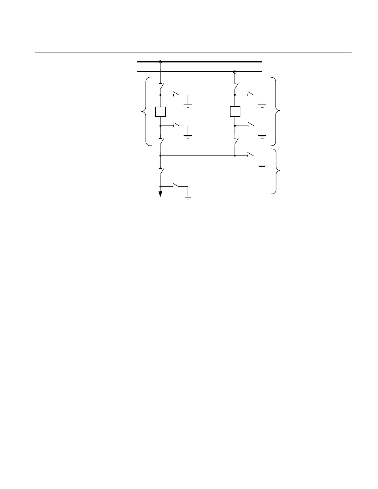
Figure 274: Switchyard layout double circuit breaker
Three types of interlocking modules per double circuit breaker bay are defined.
DB_LINE (3) is the connection from the line to the circuit breaker parts that are
connected to the busbars. DB_BUS_A (3) and DB_BUS_B (3) are the connections
from the line to the busbars.
For a double circuit-breaker bay, the modules DB_BUS_A, DB_LINE and
DB_BUS_B must be used.
Configuration setting
For application without 989 and 989G, just set the appropriate inputs to open state and
disregard the outputs. In the functional block diagram, 0 and 1 are designated
0=FALSE and 1=TRUE:
• 989_OP = 1
• 989_CL = 0
• 989G_OP = 1
• 989G_CL = 0
If, in this case, line voltage supervision is added, then rather than setting 989 to open
state, specify the state of the voltage supervision:
1MRK504116-UUS C Section 3
IED application
649
Application manual

 Loading...


