17
118
17 - Operator panel
Otherwise, four wires are used to connect the operator
panel. The operator panel terminals are labelled +, -, A
and B. Connect the plus terminal to the WMPro terminal la-
belled "+12V in/out". Connect the minus terminal to any of
the GND terminals in the WMPro. Connect A and B to the
terminals labelled A and B in the WMPro.
If communication is lost while the device is running, the
operator panel hangs. None of the buttons will have any
eect in this situation.
The operator panel has a red status LED. This LED lights up
if there is an error. The green status LED works the other
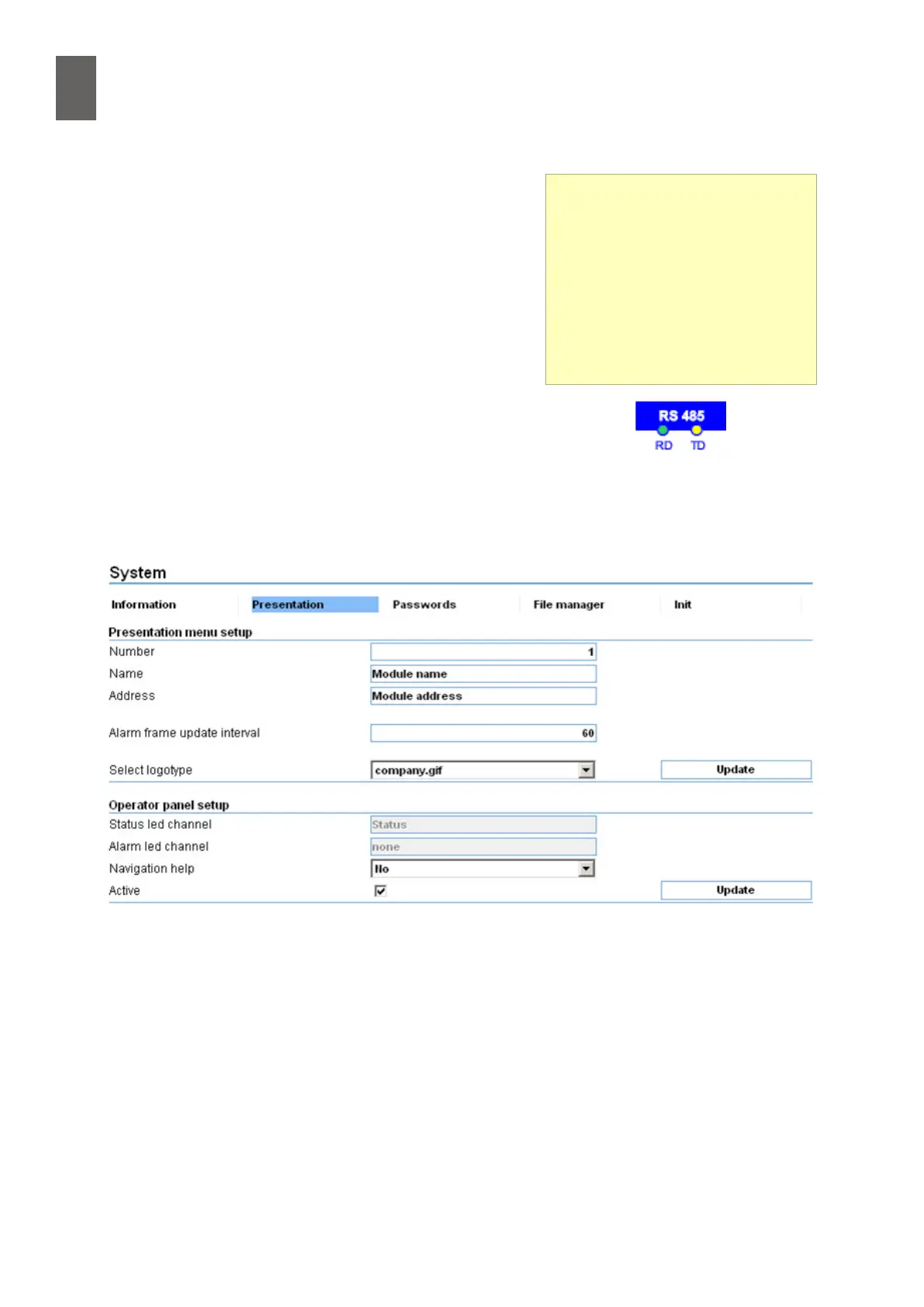
way around. You can deactivate the operator panel in
the WMPro using a setting in Presentation in the System
menu. If the Active checkbox in the Operator panel setup
section is unchecked, the WMPro does not attempt to communicate with the operator panel. If the
operator panel is connected to the RS485 port, you must check the box labelled "Enable operator
panel on GFBI interface". This results in slower communication with GFBI units.
17�3 Using the operator panel
The menus are listed vertically, so you use the up and down arrows to change menu.
If you do not use the panel for 15 minutes, the display shows the current time. To display the menu
again, press the Esc key. You can also press the key to exit a submenu or cancel a setting.
RS485
The WMPro has two LEDs for the
RS485 port. The yellow LED ashes
when the WMPro is sending data,
and the green LED ashes when it
is receiving data. With the opera-
tor panel connected and working,
every yellow ash should be fol-
lowed by a green ash.