Chapter 7 - Controller System Installation
118 Adept Python Modules User’s Guide, Rev. E
7.2 System Cable Diagram
Figure 7-1. System Cable Diagram
STOP
R
AMP
PWR
XDCS
PWR
AC
AMP
ES2
IN
1
AUX
ES1
XSLV1/
AC
CH1 CH2
24V
AUX DC RESET
XSLV2
PDU3
2
AMP DC RESET
C
I
R
C
U
I
T
B
R
E
A
K
E
R
R
ON
SmartServo IEEE-1394
1 2 3 4
SF ES HD
SW1
1.1 1.2 2.1 2.2
OK
123
XDIO
LANHPE
OFF
XSYS
CAMERA
Eth 10/100
XUSR
Device Net
XFP
RS-232/TERM
RS-232-1
XMCP
BELT ENCODER
SmartController CX
-+ -+
RS-422/485
XDC1 XDC2
24V 5A
*S/N 3562-XXXXX*
RS-232-2
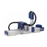
Typical Adept
Python Linear
Module
SmartController
Terminator
Installed
Front Panel
Ethernet (Eth 10/100) to PC
AC In
for
PDU3
IEEE 1394 Cable
Controller (XFP) to
Front Panel
Controller (XSYS)
to PDU3
User-Supplied
Ground Wire
Attach shield from user-supplied
cable to side of controller using
star washer and M3 x 6 screw.
Attach shield from user-
supplied cable to frame
ground on power supply.
24VDC Power from PDU (DC Output) to MB-10 #1
Switched AC Power from PDU (AC PWR AMP) to MB-10 #1
24 VDC Power from
User-Supplied
Power Supply to
Controller (XDC1)
User-Supplied
24 VDC
Power Supply
User-Supplied
Desktop or Laptop PC
Terminator
Installed
PDU3
T2 Pendant (optional)
Install terminator
if pendant not used.
Artisan Technology Group - Quality Instrumentation ... Guaranteed | (888) 88-SOURCE | www.artisantg.com