Total Access 1248 Octal T1 IMA DSLAM Installation and Maintenance Practice
3-12 61179641L4-5B
Alarm Connections
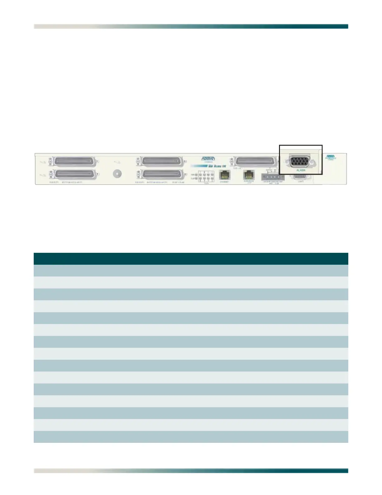
The Total Access 1248 provides an alarm port (see Figure 3-8) with three auxiliary alarm
inputs and three alarm outputs (Major, Minor, and Critical). Alarm inputs are activated by
shorting A and B contacts (closing an externally connected relay). The outputs provide both
normally open and normally closed pins (through internal relay contacts) for proper operation
with a variety of alarm panels. Each alarm event generates an autonomous TL1 message that
is transmitted via the in-band management channel to a monitoring device.
A cable with a high density DB-15 male connector on one end and a stub at the other end is
available (P/N 1196DB901L1) for wire-wrap connections to an alarm panel.
Figure 3-8. Total Access 1248 Alarm Connection
The alarm pinouts are shown in Table 3-3.
Table 3-3. Alarm Pinouts
Pin Color Contact Description
1 Red Alarm 3 Input - A
2 Red/Black Alarm 1 Input - B
3 Red/White Critical Alarm COM
4 Orange Minor Alarm COM
5 Orange/Black Major Alarm COM
6 White Alarm 3 Input - B
7 White/Black Alarm 2 Input - A
8 Black Critical Alarm NC
9 Black/White Minor Alarm NC
10 Blue/Black Major Alarm NC
11 Blue/White Alarm 2 Input - B
12 Blue Alarm 1 Input - A
13 Green/Black Critical Alarm NO
14 Green/White Minor Alarm NO
15 Green Major Alarm NO
PORTS 1-2

 Loading...