Serial interfaces
Advantech-DLoG DLT-V83 Series Manual V1.31 Page 125 of 178
11.4.2. Digital I/O interface
The Digital I/O interface is galvanically separated from the overall system. A matching
driver is integrated in the operating system. An API description as well as sample
application are available upon request. Contact your Advantech-DLoG sales
representative if necessary.
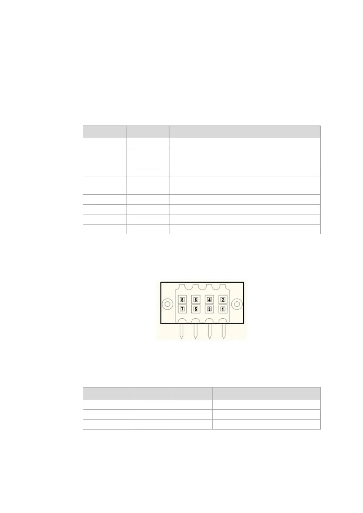
Pin assignment:
Pin Signal
1 DI1+ Provides 12 VDC / max. 8 mA
2 DI1- Input DI1 -> selectable up to max. 12 VDC / 100 Hz
filter integrated
3 DI2+ Provides 12 VDC / max. 8 mA
4 DI2- Input DI1 -> selectable up to max. 12 VDC / 100 Hz
filter integrated
5 DIO_GND GND Potential for Digital I/O application
6 DO1 Output 1: supplies 12 VDC / 20 mA
7 DO2 Output 1: supplies 12 VDC / 20 mA
8 DO3 Output 1: supplies 12 VDC / 20 mA
Fig. 11.4: Digital I/O interface pin position
Matching connectors (examples):
Manufacturer Series Order no. Description
Weidmüller B2L 3.50F 1748180000 B2L 3.50/08/180F SN BK BX
Weidmüller B2L 3.50 1847530000 B2L 3.50/08/180 SN OR BX PRT
Weidmüller B2L 3.50 1024270000 B2L 3.50/08/180 SN BK BX PRT