Table of figures
Page 166 of 178 DLT-V83 Series Manual V1.31 Advantech-DLoG
21. Table of figures
Fig. 3.1: Name plate, example .................................................................................................................................. 26
Fig. 5.1: <Power> button of the DLT-V83 ................................................................................................................. 32
Fig. 5.2: Operating elements on the DLT-V8310, 26 front keys, resistive touchscreen ............................................ 35
Fig. 5.3: Operating elements front side DLT-V8310 with PCT touchscreen ............................................................. 40
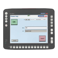
Fig. 5.4: Software keyboard ...................................................................................................................................... 43
Fig. 6.1: DLoG Config Tool main menu .................................................................................................................... 46
Fig. 6.2: Summit Client Utility menu .......................................................................................................................... 49
Fig. 6.3: Initial Laird Connection Manager dialog box ............................................................................................... 50
Fig. 6.4: LCM Configuration tab with the Manage Profiles button ............................................................................. 50
Fig. 6.5: LCM Manage Profiles dialog box with the Admin Login tab ........................................................................ 51
Fig. 6.6: Entering the LCM password: SUMMIT ....................................................................................................... 51
Fig. 6.7: WWAN driver installation, Sierra Wireless driver to C:\Util\ ........................................................................ 53
Fig. 6.8: WWAN driver installation, WWAN 32-bit .................................................................................................... 54
Fig. 6.9: WWAN driver installation, Run as administrator ......................................................................................... 54
Fig. 6.10: WWAN driver installation, COM port ......................................................................................................... 55
Fig. 6.11: Driver configuration, open device manager .............................................................................................. 56
Fig. 6.12: Driver configuration, Sierra wireless card using Vodafone as example .................................................... 56
Fig. 6.13: Function test GSM / GPS, Network and Sharing Center .......................................................................... 57
Fig. 6.14: Function test GSM / GPS, Connect to the Internet ................................................................................... 58
Fig. 6.15: Function test GSM / GPS, wireless........................................................................................................... 58
Fig. 6.16: Function test GSM / GPS, telephone number ........................................................................................... 59
Fig. 6.17: Function test GSM / GPS, network connections ....................................................................................... 59
Fig. 6.18: Function test GSM / GPS, test connection ............................................................................................... 60
Fig. 6.19: Function test GSM / GPS, test connection status ..................................................................................... 60
Fig. 6.20: Deleting the GPS test connection ............................................................................................................. 61
Fig. 6.21: GPS test ................................................................................................................................................... 61
Fig. 6.22: GPS test, COM4 ....................................................................................................................................... 62
Fig. 6.23: GPS test position data .............................................................................................................................. 62
Fig. 6.24: GPS receiver (optional) ............................................................................................................................ 63
Fig. 6.25: Ext. GPS receiver, display example during installation ............................................................................. 63
Fig. 6.26: Start of the IXXAT driver installation ......................................................................................................... 64
Fig. 6.27: iManager: GPIO Bank Control .................................................................................................................. 65
Fig. 6.28: Network Connection Properties, Advanced .............................................................................................. 67
Figure 6.29: iManager: Network Connection Properties, Power Management ......................................................... 67
Fig. 6.30: Network Connection Properties, Advanced .............................................................................................. 68
Figure 6.31: iManager: Network Connection Properties, Power Management ......................................................... 68
Fig. 6.32: Network Connection Properties, Advanced .............................................................................................. 68
Fig. 7.1: DC connection cable with Phoenix contact connector ................................................................................ 74
Fig. 7.2: Position of the ground bolt .......................................................................................................................... 76
Fig. 7.3: Angled AC power cable .............................................................................................................................. 77
Fig. 7.4: Cable cover with integrated UPS battery (optional) .................................................................................... 80
Fig. 7.5: Dummy grommets and cable grommets for various cable diameters ......................................................... 80
Figure 6: Cable grommets and dummy grommets .................................................................................................... 81
Fig. 7.7: Example cable grommet ............................................................................................................................. 82
Fig. 7.8: The power supply cable, fit with a cable grommet, in the strain relief rail ................................................... 82
Fig. 7.9: Unused cable outlets sealed off .................................................................................................................. 83
Fig. 7.10: Power supply cable with cable clip on the strain relief rail ........................................................................ 83
Fig. 7.11: Detailed view cable clips on strain relief rail ............................................................................................. 83
Fig. 7.12: Cables and dummy grommets .................................................................................................................. 84
Fig. 7.13: Screwing the cable cover into place ......................................................................................................... 85
Fig. 7.14: Cable cover with integrated UPS battery .................................................................................................. 86
Fig. 7.15: Pressure compensation element - Do not modify or remove! ................................................................... 87
Fig. 8.1: DC power supply connector with connector detail view .............................................................................. 89
Fig. 8.2: External connections 12/24/48 VDC devices detail view ............................................................................ 91
Fig. 8.3: DC connection cable, original Advantech-DLoG ......................................................................................... 92