ACCEPTANCE TESTING
7-25
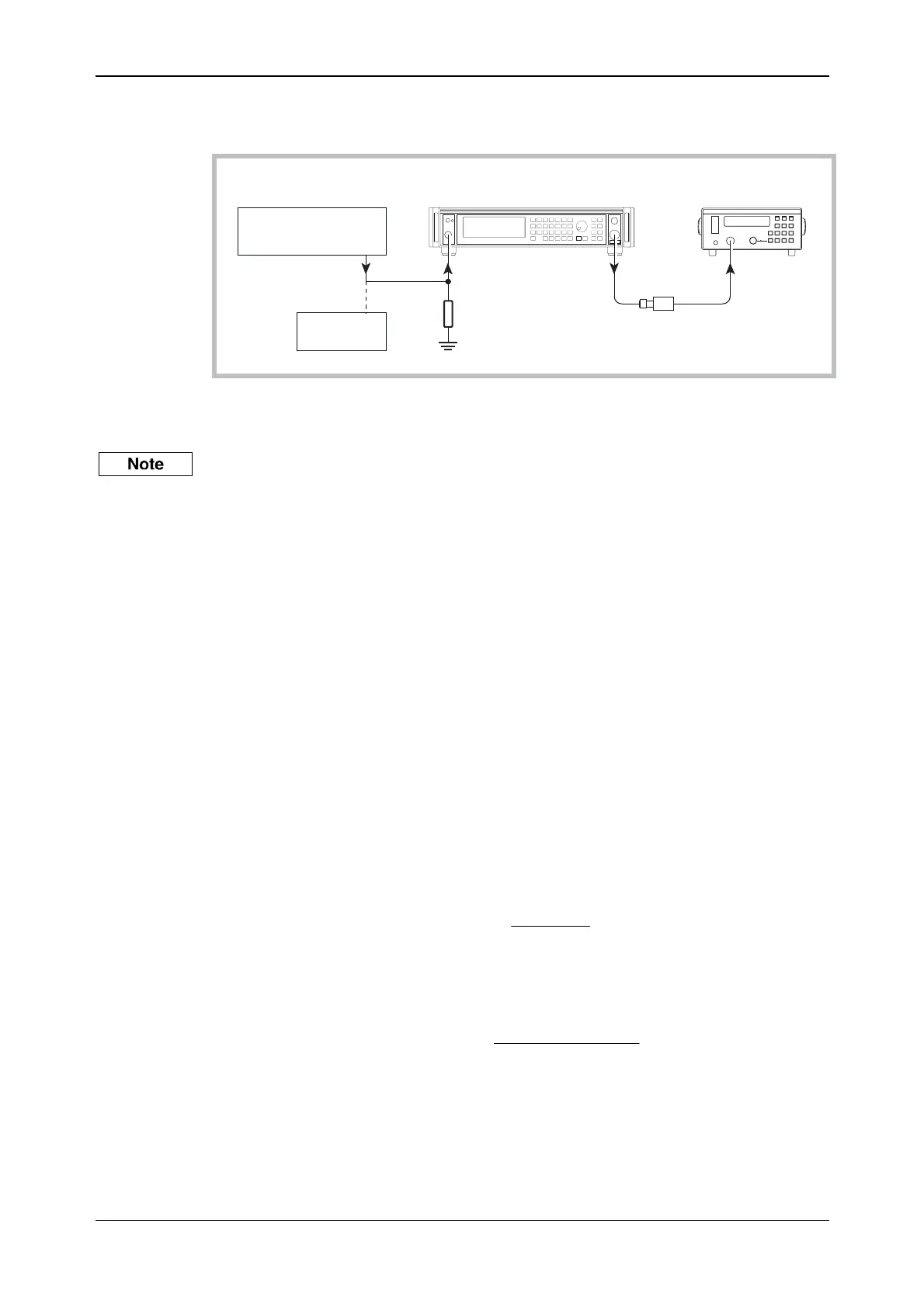
0 Hz (DC)
UUT
6960B
RF power meter
6912
Power sensor
C2369
RF
OUTPUT
EXT MOD
INPUT
OUTPUT
Temporary
connection
SENSOR
INPUT
Function generator
DVM
50 loadΩ
Fig. 7-10 0 Hz external AM and distortion test set-up
(9) Connect the test equipment as shown in Fig. 7-10.
(10) Set the function generator to +1.4142 V DC (+1 V DC for units with Option 10).
(Temporarily connect the function generator output to the DVM and set this voltage as close
as possible to +1.4142 V (+1 V DC for units with Option 10).)
(11) Measure the power on the power meter.
P1 = _____
(12) Set the function generator to
−1.4142 V DC (−1 V DC for units with Option 10).
(Temporarily connect the function generator output to the DVM and set this voltage as close
as possible to
−1.4142 V (−1 V DC for units with Option 10).)
(13) Measure the power on the power meter.
P2 = _____
(14) Subtract P2 from P1 (= x)
(15) Calculate the modulation depth using the formula:
⎭
⎬
⎫
⎩
⎨
⎧
−
−
+
−
=
x/20)(
x/20)(
101
101
(%)AM
(16) Calculate the 0 Hz response relative to 1 kHz using the following formula, recording the
result in Table 7-34:
20
6
15
10
log
()
()
Figure recorded in
Figure recorded in
⎧
⎨
⎩
⎫
⎬
⎭
(17) Set the UUT RF level to +7 dBm and repeat (4) to (16) using Table 7-35.
To measure the AM depth at DC, it is necessary to use the DC offset facility on the function
generator, proceeding as follows:
 Loading...