LOCAL OPERATION
4-4
Introduction
All operations of the signal generator are carried out from the front-panel keyboard which is
color-coded. An extensive suite of utility menus make this a very versatile instrument. The
built-in GPIB and RS-232 interfaces enable the instrument to be remotely operated.
Front-panel controls and connectors
Parameters are selected by means of keys which have their functions printed on them, a numerical
key pad and a rotary control knob. The numerical keys are used to set parameters to specific
values which can also be varied in steps of any size by using the [⇑÷10] and [⇓×10] keys or the
rotary control knob.
Connectors
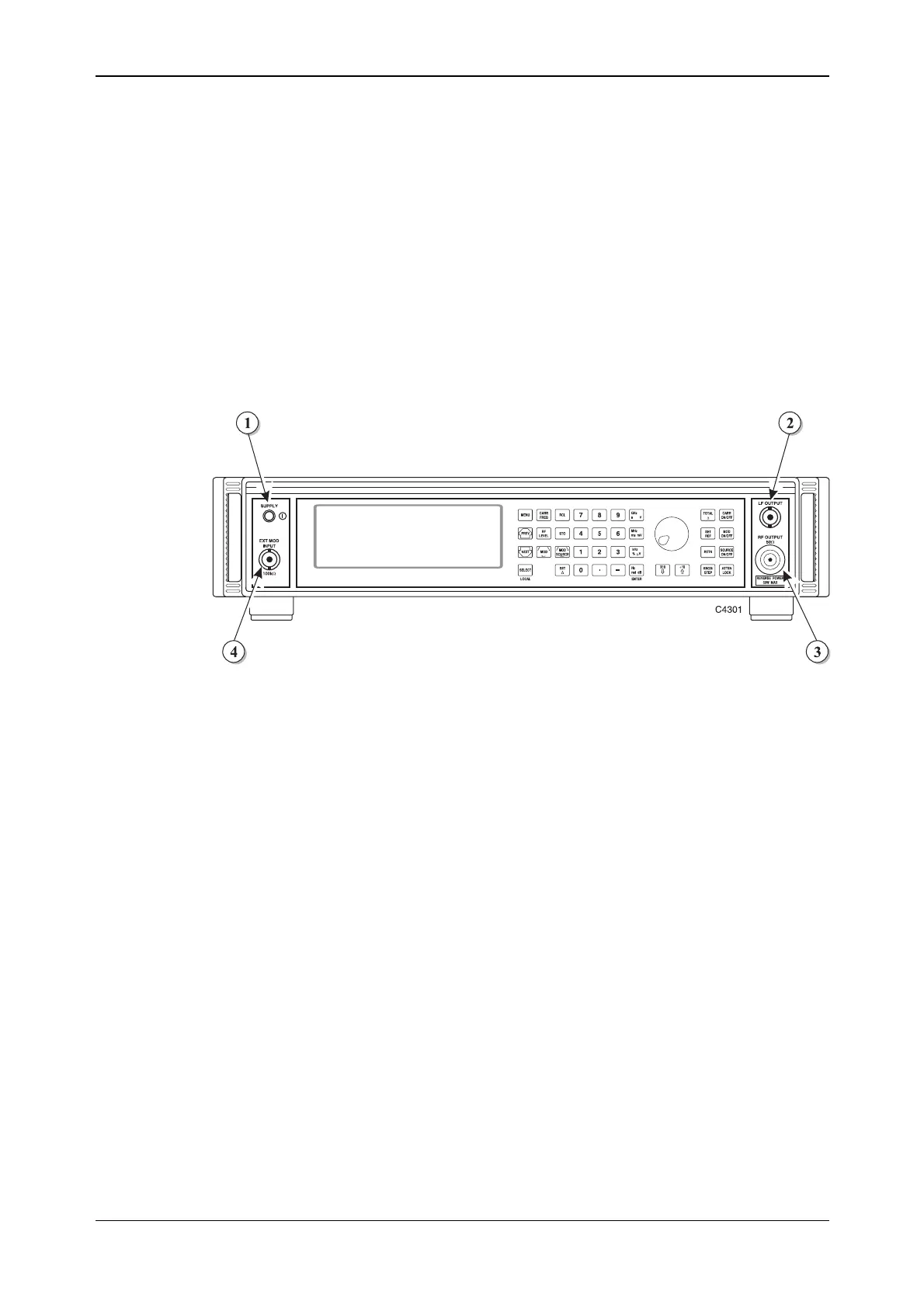
The front-panel connectors are shown in Fig. 4-1 below:
Fig. 4-1 2025 front panel showing SUPPLY switch and connectors
(1) SUPPLY switch Switches the supply on and off using a press on, press off
action.
(2) LF OUTPUT 600 Ω BNC socket that monitors the modulation oscillator.
With Option 5 this socket is fitted on the rear panel.
(3) RF OUTPUT 50 Ω N-type socket. Protected against the application of
reverse power of up to 50 W.
With Option 5 this socket is fitted on the rear panel.
(4) EXT MOD INPUT 100 kΩ BNC socket. An independent input that allows an
external modulating signal to be applied.
With Option 5 this socket is fitted on the rear panel.
Note: connector positions differ for Options 7 and 11 − see Annex A (Option 7) and Annex B (Option 11).