ACCEPTANCE TESTING
7-35
Carrier harmonics
Specification
As the standard instrument below +7 dBm.
Harmonics:
Typically better than
−25 dBc for RF levels up to 6 dB below the
maximum specified output
Test equipment
Description Minimum specification Example
Spectrum
analyzer
DC to 7.6 GHz frequency coverage Anritsu MS2602A
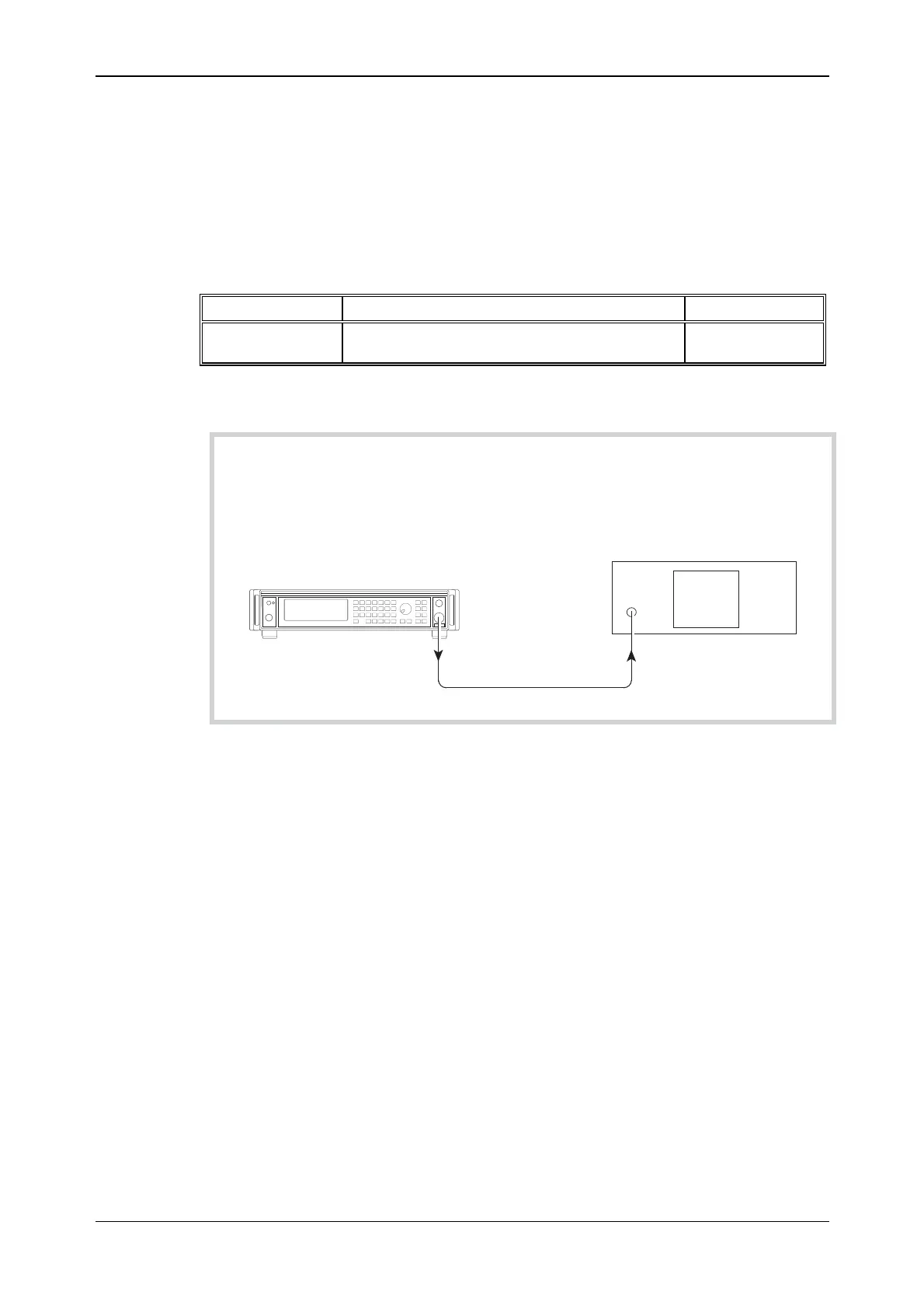
Test procedure
UUT
Spectrum analyzer
C5803
RF OUTPUT
RF INPUT
Fig. 7-18 Carrier harmonics test set-up
(1) Press CAL on the spectrum analyzer.
(2) Connect the test equipment as shown in Fig. 7-18.
(3) On the UUT set:
[CARR FREQ] 10 [kHz]
[RF LEVEL] −4 [dB]
(4) Measure the level of the second and third harmonics on the spectrum analyzer at each of the
carrier frequencies shown in Table 7-52.
(5)
Set the UUT RF level to +7 dBm and repeat (4) using Table 7-53.
(6)
Set the UUT RF level to +13 dBm and repeat (4) using Table 7-54.
(7)
Set the UUT RF level to +19 dBm and repeat (4) using Table 7-55.