CONTROLS AND CONNECTORS
4-7
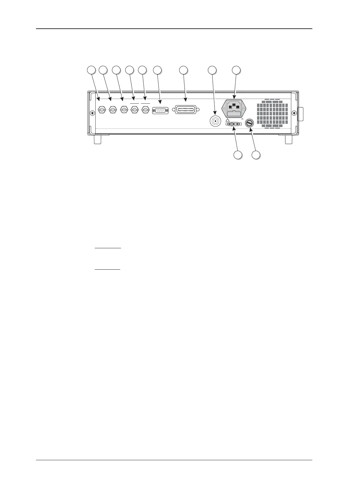
Rear-panel connectors
The rear-panel connectors are shown in Fig. 4-3 below.
50-400Hz
50-60Hz
100-120V
210-240V
POWER SUPPLY
IEEE 488.2
RF OUTPUT
50W
DC
SUPPLY
11-32V
6A MAX
DC
SUPPLY
FUSE
T10AH250V
TRIGGER
2FSK
PULSE I/P
4FSK
FREQ STD
IN-OUT
LF
OUTPUT
EXT MOD
INPUT
RS232
200VA MAX
FUSE RATING T2AL250V
C5704
27 28 313029
32 33 34 35
3637
!
Fig. 4-3 Instrument rear panel showing connectors
(27) EXT MOD INPUT
(optional)
An Option 5 BNC socket which allows an external
modulating signal to be applied. When fitted, replaces the
front-panel socket.
(28) LF OUTPUT (optional) An Option 5 BNC socket which monitors the modulation
oscillator. When fitted, replaces the front-panel socket.
(29) FREQ STD IN-OUT BNC socket for the input of external standard frequencies of
either 1 MHz or 10 MHz. Can also supply a 10 MHz
internal standard output.
(30) PULSE I/P
4FSK
10 kΩ BNC socket which accepts a pulsed input. Also used
as one logic input (the other is the TRIGGER input) for
4FSK modulation.
(31) TRIGGER
2FSK
BNC socket which has three uses; in priority order these are:
FSK logic input
Memory sequencing
Sweep trigger
(32) RS232 9-way RS-232 connector for remote control of the
instrument. For contact allocation see Chapter 2.
(33) IEEE 488.2 24-pin socket accepts the standard GPIB connector to allow
remote control of the instrument. For contact allocation see
Chapter 2.
(34) RF OUTPUT (optional) An Option 5 50 Ω N-type socket. When fitted, replaces the
front-panel socket.
(35) POWER SUPPLY 3-pin plug integral with fuse holder. Mates with AC supply
lead socket.
(36) DC SUPPLY FUSE
(optional)
When Option 2 fitted, fuses the DC input socket.
(37) DC input (optional) When Option 2 fitted, the socket allows operation from an
external 11 to 32 V DC source. For contact polarity see
Chapter 2.