GENERAL
4-44
RF level offsets
To use the RF level offsets utility first ensure that the instrument is unlocked to Level 1 using
Util 80: Protection Lock/Unlock. This utility enables you to offset the RF output level to
compensate for cable or switching losses, or to standardize a group of instruments so that they
give identical measurements. The offsets do not change the displayed RF level but do change the
RF output level. Setting a negative offset decreases the level from the RF OUTPUT socket.
One offset is allowed in each of the following frequency ranges (applicable to all instruments
except where shown):
9 kHz
−
150 MHz
150 MHz
−
300 MHz
300 MHz
−
600 MHz
600 MHz
−
1.2 GHz
1.2 GHz
−
2.05 GHz (2023B only)
1.2 GHz
−
2.51 GHz (2025 only)
Proceed as follows:
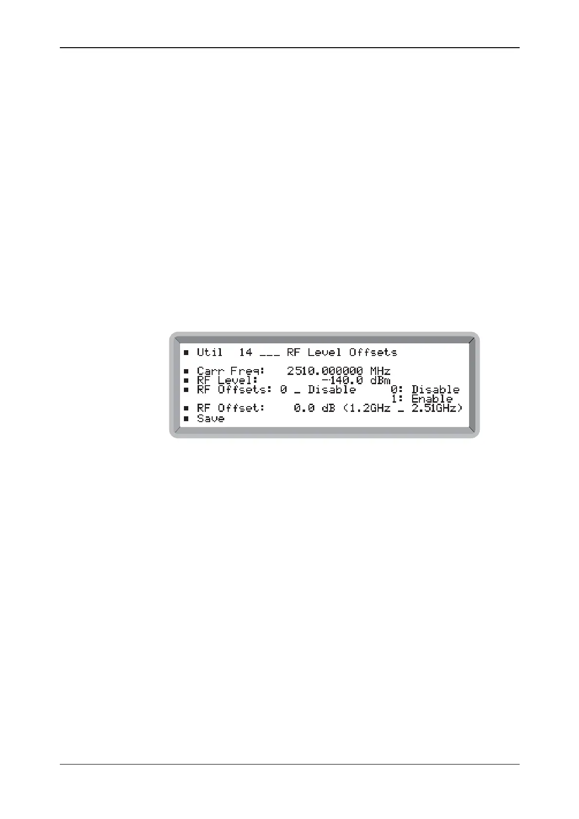
(1) Select the Util 14: RF Level Offsets menu. This shows the selected RF level offset for the
currently selected carrier frequency (see Fig. 4-38).
B6314UTIL14
Fig. 4-38 RF level offsets menu
(2) Enter the required carrier frequency (which automatically selects the appropriate frequency
range).
(3) Set the required positive or negative RF offset in the range 0 to 15.0 dB to a resolution of
0.1 dB using either the key pad or control knob. The applicable frequency range follows in
brackets.
(4) Repeat steps (2) and (3) above for each required additional range.
(5) Enter 0 to disable or 1 to enable all ranges.
(6) Select Save which causes * Saved * to be displayed. Now all your offsets are saved in
non-volatile memory so that when subsequently the instrument is switched on again it is set
with your specified offsets.
Note that setting an RF level offset may cause the RF level displayed to decrease, so that the
absolute limits of the instrument are not exceeded.