OPTION 7 FAST PULSE MODULATION
Annex-A-3
Controls and connectors
The following sections replace those with the same titles in Chapter 4 in the main body of the
manual.
Front-panel connectors
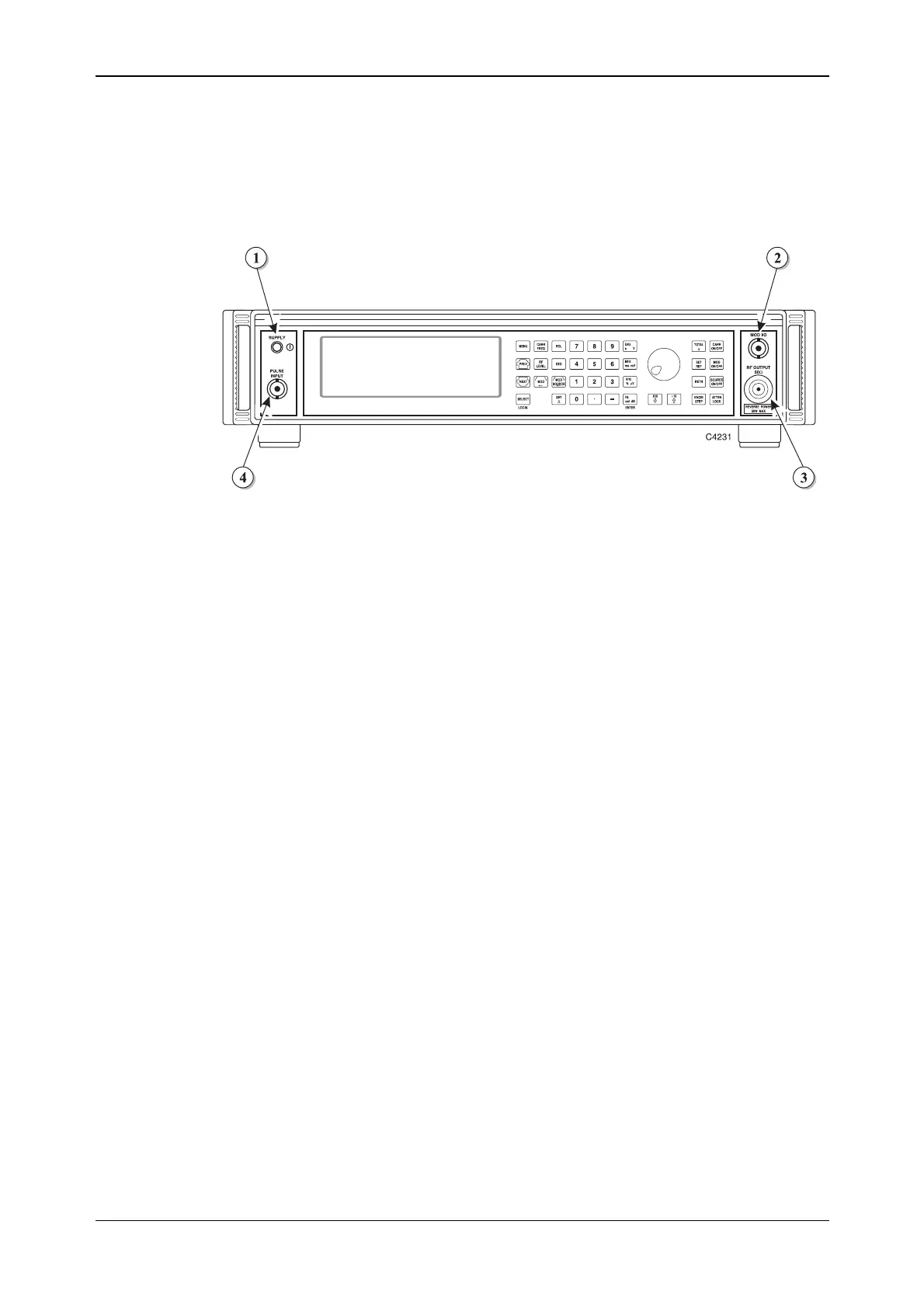
The front-panel connectors are shown in Fig. A-0 below:
Fig. A-1 2023B front panel showing SUPPLY switch and connectors
(1) SUPPLY switch Switches the supply on and off using a press on, press off
action.
(2) MOD I/O
100 kΩ BNC connector, which allows an external
modulating signal to be applied. Also provides a modulation
oscillator output from a 600 kΩ source impedance.
With Option 5 this connector is fitted on the rear panel.
(3) RF OUTPUT
50 Ω N-type socket. Protected against the application of
reverse power of up to 50 W.
With Option 5 this socket is fitted on the rear panel.
(4) PULSE INPUT
50 Ω BNC socket, which accepts a pulsed input.
With Option 5 this socket is fitted on the rear panel.