ACCEPTANCE TESTING
7-26
Pulse modulation (not Option 7 or 11)
Specification
Carrier frequency range:
32 MHz to 2.51 GHz, usable to 10 MHz
RF level range:
Maximum guaranteed output is reduced to +8 dBm when pulse
modulation is selected
RF level accuracy:
Maximum additional uncertainty is
±0.5 dB
On/off ratio:
Better than 40 dB
Better than 45 dB below 1.2 GHz
Rise and fall time:
Less than 10
μs
Test equipment
Description Minimum specification Example
Power meter
±0.1 dB from 9 kHz to 2.51 GHz
Aeroflex 6960B
and 6912
Spectrum
analyzer
Frequency coverage 32 MHz to 2.51 GHz Anritsu MS2602A
50 Ω load
(termination)
1 W, 50 Ω nominal impedance, DC to 2.51 GHz
Lucas Weinschel
M1404N
Oscilloscope 100 MHz bandwidth Tektronix
TAS 465
Function
generator
DC to 10 kHz square wave Agilent 3325B
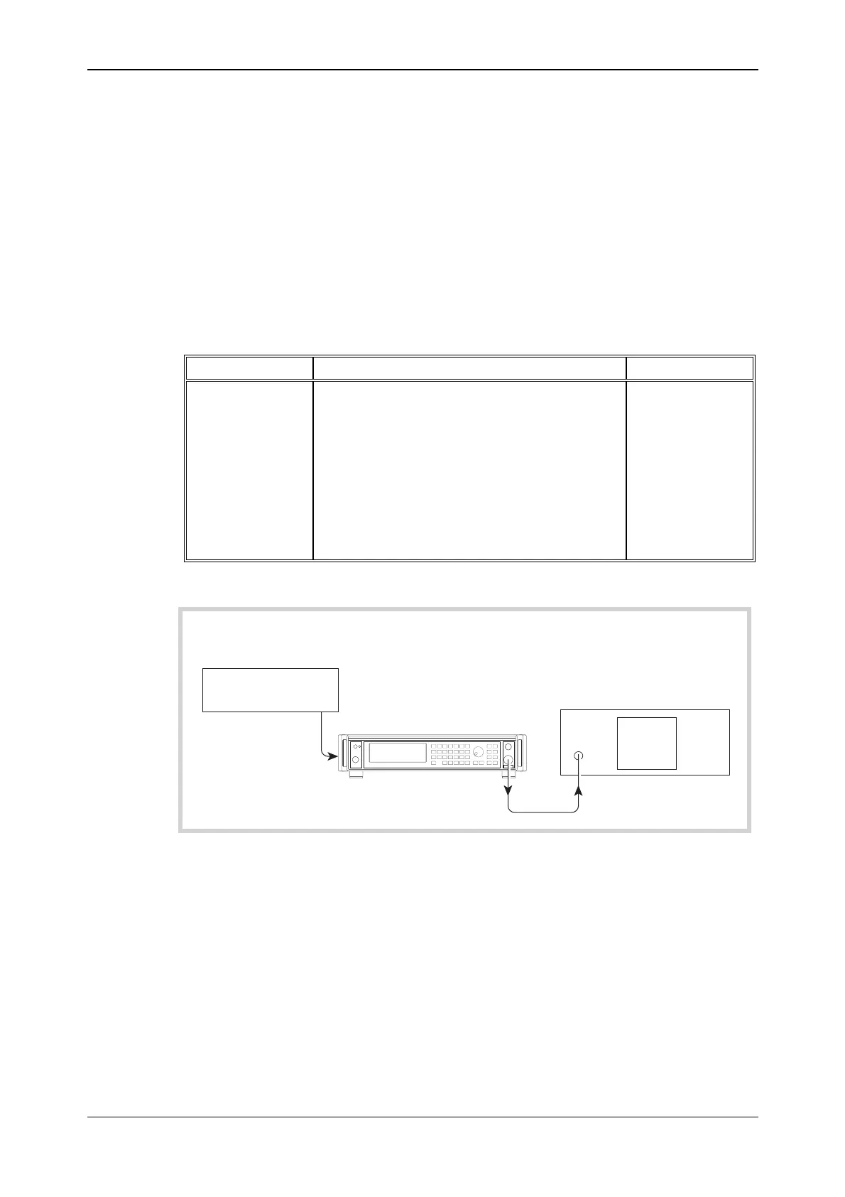
Pulse modulation RF level frequency response
UUT
C5804
RF
OUTPUT
PULSE
I/P
(Rear panel)
OUTPUT
Function generator
Spectrum analyzer
RF INPUT
Fig. 7-11 Pulse modulation test set-up
Test procedure
(1) Perform AUTO ZERO and AUTO CAL on the power meter.
(2) Connect the test equipment as shown in Fig. 7-11.