INSTALLATION
2-6
General purpose interface bus (GPIB)
The GPIB interface built into the instrument enables the signal generator to be remotely controlled
to form part of an automatic measuring system, as well as being used to dump memory (cloning)
from one instrument to another.
GPIB cable connection
Connection to other equipment that has a 24-way connector to IEEE Standard 488 is made using
the rear-panel IEEE 488-2 socket. For this purpose the GPIB cable assembly, available as an
optional accessory (see ‘Versions and accessories’ at the end of Chapter 1), may be used.
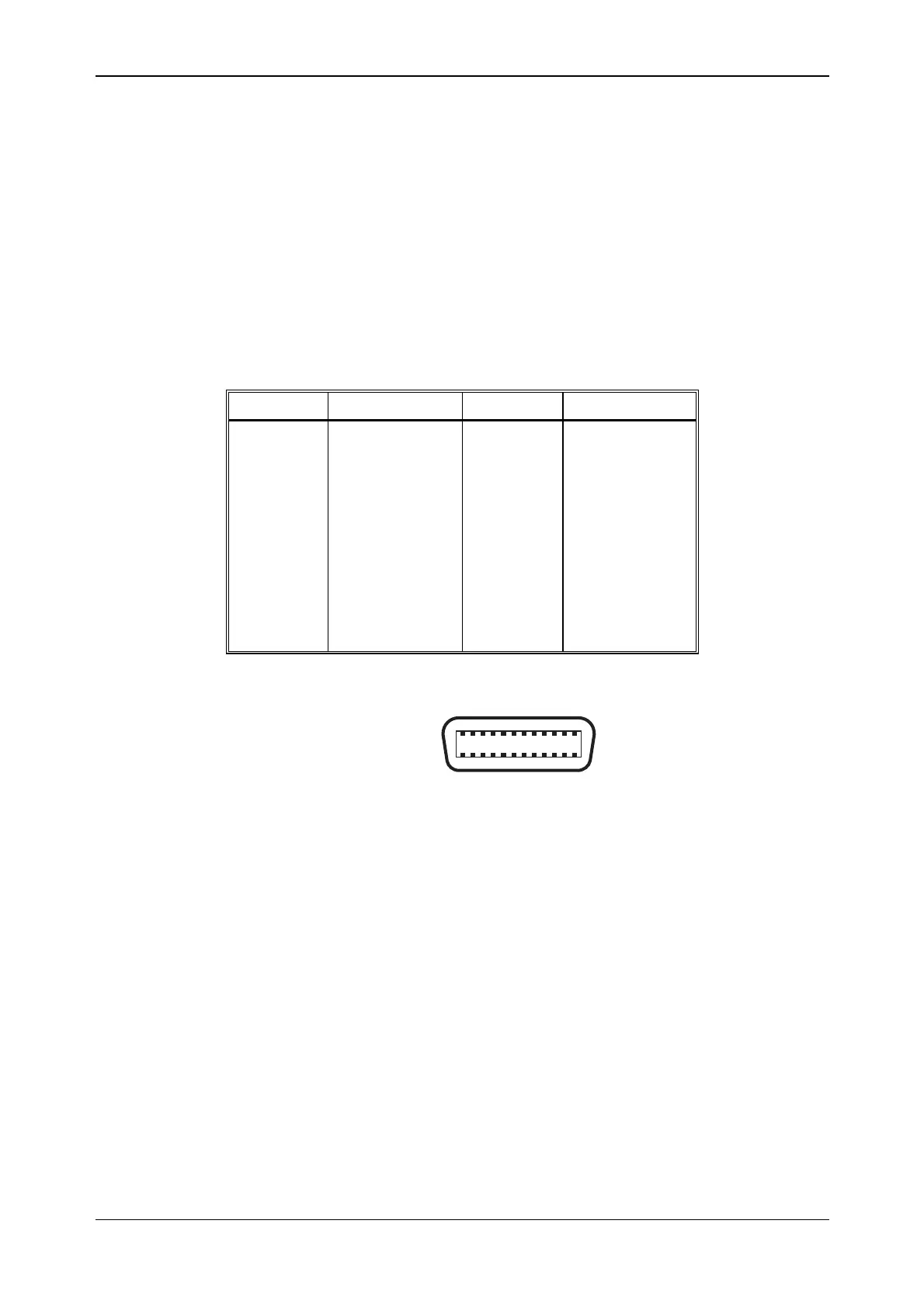
GPIB connector contact assignments
The contact assignments of the GPIB cable connector are as given in the table below and shown in
Fig. 2-2.
Contact Function Contact Function
1
2
3
4
5
6
7
8
9
10
11
12
Data I/O 1
Data I/O 2
Data I/O 3
Data I/O 4
EOI
DAV
NRFD
NDAC
IFC
SRQ
ATN
Ground shield
13
14
15
16
17
18
19
20
21
22
23
24
DataI/O 5
DataI/O 6
DataI/O 7
DataI/O 8
REN
Pair with 6
Pair with 7
Pair with 8
Pair with 9
Pair with 10
Pair with 11
Logic ground
12 1
24 13
Fig. 2-2 GPIB connector contact assignments (viewed from rear of instrument)