INSTALLATION
2-7
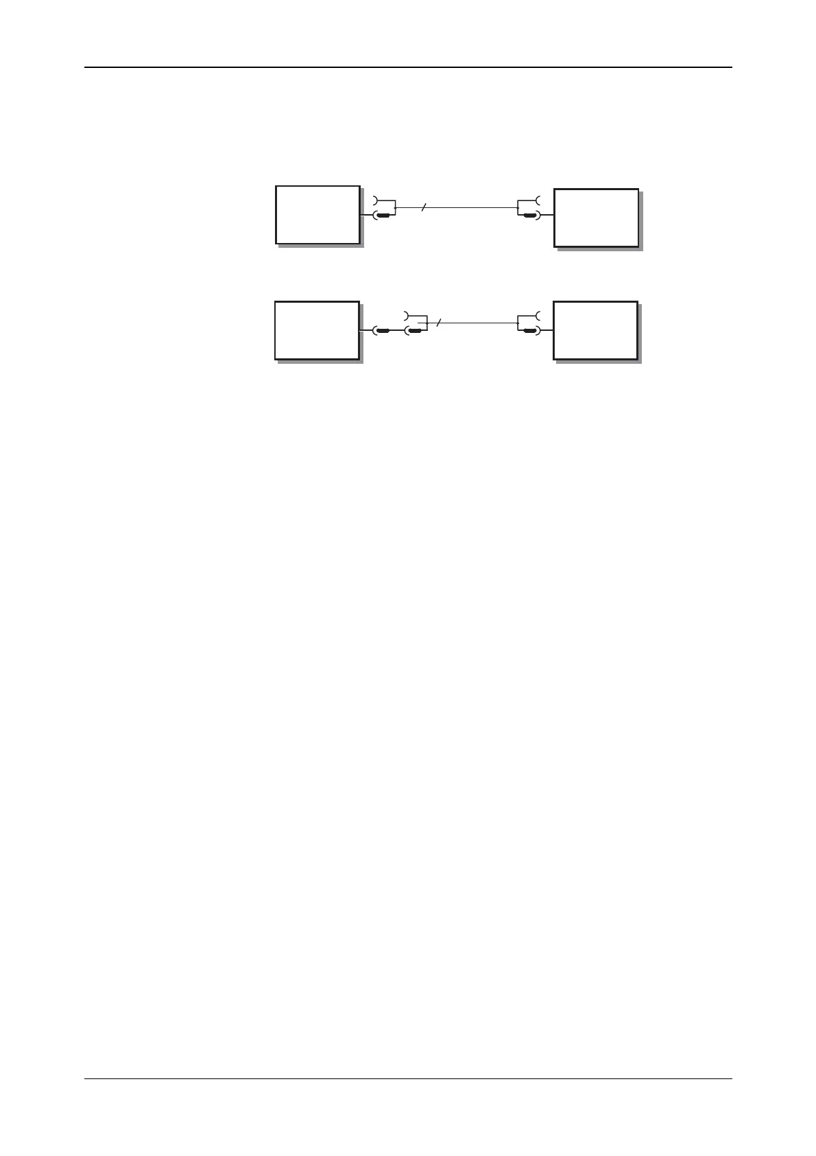
IEEE to IEC conversion
An optional IEEE to IEC adapter is also available (see ‘Accessories’ at the end of Chapter 1) for
interfacing with systems using a 25-way bus connector to IEC Recommendation 625. The method
of use is shown in Fig. 2-3.
INSTRUMENT
(IEEE
CONNECTOR)
EQUIPMENT
WITH IEEE
CONNECTOR
INSTRUMENT
(IEEE
CONNECTOR)
EQUIPMENT
WITH IEC
CONNECTOR
24
25
IEEE LEAD
IEEE to IEC
ADAPTER
IEC LEAD
46883-408
C4400
Fig. 2-3 IEEE to IEC conversion
Interface bus connection
The cables for the interface bus use special male-female connectors at both ends. This allows
several connectors to be stacked one on top of another, permitting several cables to be connected
to the same source and secured by a lockscrew mechanism. Too large a stack, however, may form
a cantilevered structure, which might cause damage and should be avoided. The piggyback
arrangement permits star or linear interconnection between the devices with the restriction that the
total cable length for the system must be:
(1) No greater than 20 m (65 ft).
(2) No greater than 2 m (6 ft) times the total number of devices (including the controller)
connected to the bus.