OPTION 7 FAST PULSE MODULATION
Annex-A-4
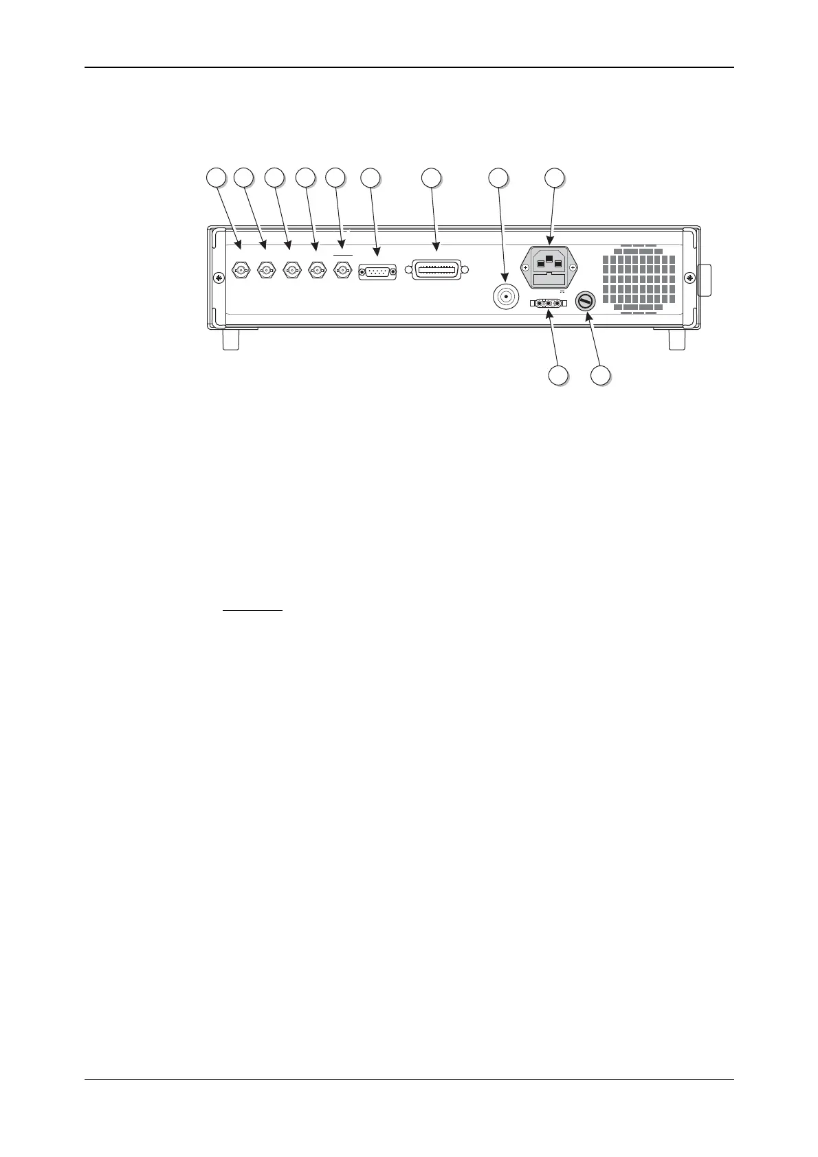
Rear-panel connectors
The rear-panel connectors are shown in Fig. A-2 below.
IEEE 488.2
TRIGGER
2FSK
4FSK
FREQ STD
IN-OUT
PULSE
INPUT
MOD
I/O
RS232
C5706
27 28 313029
32 33 34 35
3637
50-400Hz
50-60Hz
100-120V
210-240V
POWER SUPPLY
200VA MAX
FUSE RATING T2AL250V
DC
SUPPLY
11-32V
6A MAX
DC
SUPPLY
FUSE
T10AH250V
Fig. A-2 Instrument rear panel showing connectors
(27) MOD I/O (optional) An Option 5 BNC socket that, when fitted, replaces the
front-panel MOD I/O socket.
(28) PULSE INPUT
(optional)
An Option 5 BNC socket that, when fitted, replaces the
front-panel PULSE INPUT socket.
(29) FREQ STD IN-OUT BNC socket for the input of external standard frequencies of
either 1 MHz or 10 MHz. Can also supply a 10 MHz
internal standard output.
(30) 4FSK BNC socket used as one logic input (the other is the 2FSK
input) for 4FSK modulation.
(31) TRIGGER
2FSK
BNC socket that has three uses; in priority order these are:
FSK logic input
Memory sequencing
Sweep trigger.
(32) RS232 9-way RS-232 connector for remote control of the
instrument. For contact allocation see Chapter 2.
(33) IEEE 488.2 24-pin socket accepts the standard GPIB connector to allow
remote control of the instrument. For contact allocation see
Chapter 2.
(34) RF OUTPUT (optional) An Option 5 50 Ω N-type socket. When fitted, replaces the
front-panel RF OUTPUT socket.
(35) Power supply 3-pin plug integral with fuse holder. Mates with AC supply
lead socket.
(36) DC supply fuse
(optional)
When Option 2 fitted, fuses the DC input socket.
(37) DC input (optional) When Option 2 fitted, the socket allows operation from an
external 11 to 32 V DC source. For contact polarity see
Chapter 2.