DETAILED OPERATION
4-28
Pulse modulation selection (with/without Option 9)
Pulse modulation may be selected in addition to any other normal modulation modes. The
instrument uses an external source to pulse the waveform or (Option 9 only) can generate pulses
internally, either free-running or externally triggered. The external source is applied to the front-
panel PULSE INPUT socket.
See below for using pulse modulation in a standard instrument. See page 4-30 for using pulse
m
odulation when Option 9 is fitted.
Pulse modulation (standard, without Option 9)
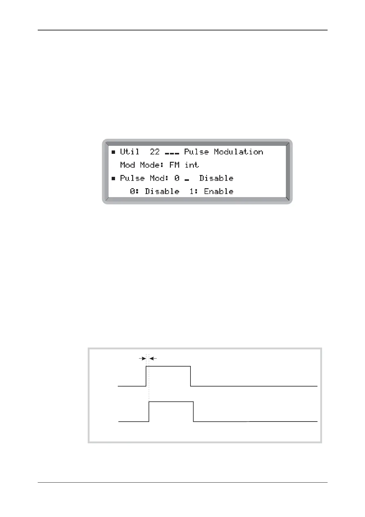
(1) Select the Util 22: Pulse Modulation menu. This shows the currently selected modulation
mode against Mod Mode: (see Fig. 4-24).
B2060UT022
Fig. 4-24 Pulse modulation menu (standard)
Modulation off
(2) Highlight Pulse Mod: and enter 0 on the keypad (no terminator is required) to disable
internal and external pulse modulation.
(3) Press [MOD] to return to the main screen. Pulse is not displayed.
External modulation
(4) Highlight Pulse Mod: and enter 1 on the keypad (no terminator is required) to enable
external modulation. The display changes to show the current modulation plus Pulse (for
example, Mod Mode: AM int + FM ext + Pulse ext).
(5) Press [MOD] to return to the main screen with Pulse displayed together with its ON state.
When ON the carrier is controlled by the logic level applied to the PULSE INPUT socket. A
logical ‘1’ (5 V) allows carrier output, a logical ‘0’ (0 V) suppresses it. Turning pulse mod OFF
effectively applies a logical ‘1’, allowing carrier output (see Fig. 4-25).
Propagation delay
PULSE
OUTPUT
EXT
PULSE
INPUT
C6069
Fig. 4-25 External pulse modulation