CONTROLS AND CONNECTORS
4-5
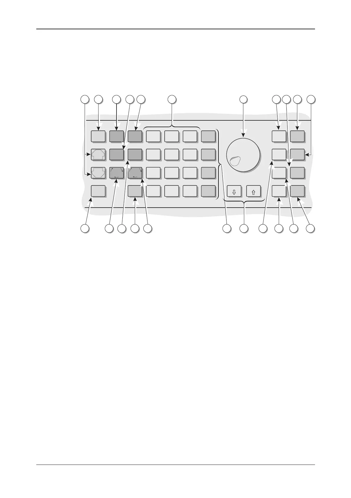
Keyboard
The keyboard is functionally color-coded. The keys for the primary functions of carrier
frequency, level and modulation are dark gray. Secondary functions such as unit selection and
on/off keys are medium gray. Menu selection, which plays such a prominent part in this
instrument, has keys which are colored blue.
The front-panel keyboard is shown in Fig. 4-2 below:
X10
KNOB/
STEP
RETN
SET
REF
TOTAL
Δ
SET
Δ
Hz
rad dB
kHz
%Vμ
MHz
ms mV
GHz
sV
CARR
FREQ
RF
LEVEL
MENU
PREV
NEXT MOD
SELECT
LOCAL ENTER
RCL
7
4
1
0
.
-
8
5
2
9
6
3
STO
MOD
SOURCE
ATTEN
LOCK
SOURCE
ON/OFF
MOD
ON/OFF
CARR
ON/OFF
÷10
C2314
5
26 1618202325
24
22 21 19 17
156 7 10 11 1412 1398
Fig. 4-2 Instrument front panel showing keyboard
(5) [PREV] A key used to scrolls backwards through a menu list or the
function list.
[NEXT] A menu key used to scroll forwards through a menu list or
the function list.
(6) [MENU] Selects the main utility menu, or within utility menus steps
back up through the menus.
(7) [CARR FREQ] Selects carrier frequency as the current function and causes
the main screen to be displayed.
(8) [RF LEVEL] Selects RF level as the current function and causes the main
screen to be displayed.
(9) [RCL] Used to recall a previously stored instrument setting from
memory.
(10) Numerical key pad For entering the value of a selected parameter. Minus sign
and decimal point are included.
(11) Control knob When enabled by the [KNOB/STEP] key, adjusts the value
of the selected parameter.
(12) [TOTAL Δ] While the key is held down, displays the total shift from the
keyed-in value.
(13) [SOURCE ON/OFF] Switches the current modulation source on and off.
(14) [CARR ON/OFF] Switches the carrier output on and off.
(15) [MOD ON/OFF] Switches ALL modulation on and off.
(16) [ATTEN LOCK] Holds the attenuator at the current setting with Atten Lock
displayed. Allows the RF level to be decreased by a further
10 dB without the step attenuator operating.