ACCEPTANCE TESTING
7-9
Attenuator accuracy
(not required for instruments with Option 1)
The following test confirms that the attenuator performs to the published performance
specification. In the event of the receiver/down-converter not being available, an alternative
method to functionally test the individual pads is also suggested. (See ‘Alternative attenuator
funct
ional test’.)
Test procedure
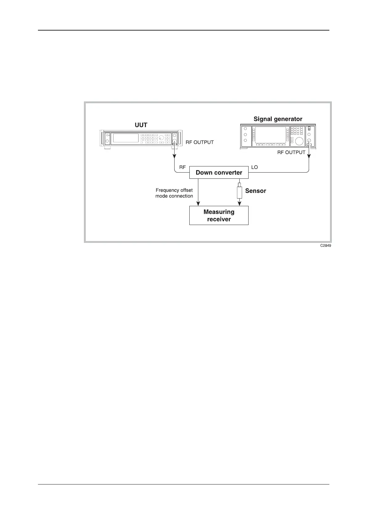
Fig. 7-2 RF output test set-up
(1) Connect the test equipment as shown in Fig. 7-2.
(2) On the UUT set:
[CARR FREQ] 2.6 [MHz]
[RF LEVEL] 0 [dB]
[SET Δ]
[RF LEVEL] (to select [Levl Step]) 11 [dB]
[RF LEVEL]
(3) Tune the receiver to 2.6 MHz and record the output level measured in Table 7-8, checking
th
at the result is within specification.
(4) Set the UUT RF level to
−4.1 dBm. Measure the received level and record the result in
Table 7-8, checking that the result is within specification.
(5) Decrement the UUT, using the [×10 Ø] key, in 11 dB steps down to an RF level of
−103.1 dBm measuring the received level at each step shown in Table 7-8, checking that the
results are within specification.
(6) Set the UUT to carrier frequency 880.1 MHz and repeat (2) to (5) using Table 7-9.
(7)
Set the UUT to carrier frequency 1199 MHz and repeat (2) to (5) using Table 7-10.
Not
e that the following test frequencies are for 2023B and 2025 only. The down converter is
automatically enabled when testing frequencies above 1300 MHz.
(8) Set the local oscillator to +8 dBm at a carrier frequency of 62 MHz less than the test
frequency (i.e. 1813 MHz).
(9) On the receiver, enter the local oscillator frequency followed by the test frequency.
(10) Set the UUT to carrier frequency 1875 MHz and repeat (2) to (5) using Table 7-11.
(11)
Set the UUT to carrier frequency 2050 MHz (2023B) or 2510 MHz (2025) and repeat (2) to
(5) using Table 7-12.