DETAILED OPERATION
4-29
FSK selection
The instrument accepts one or two logic level inputs to produce an FSK modulated output signal.
The input data is sampled at 156 kHz and produces a 2 or 4 level shift waveform which is filtered
by a 20 kHz Bessel filter and applied to the carrier. Frequency shift keying is selected as follows:
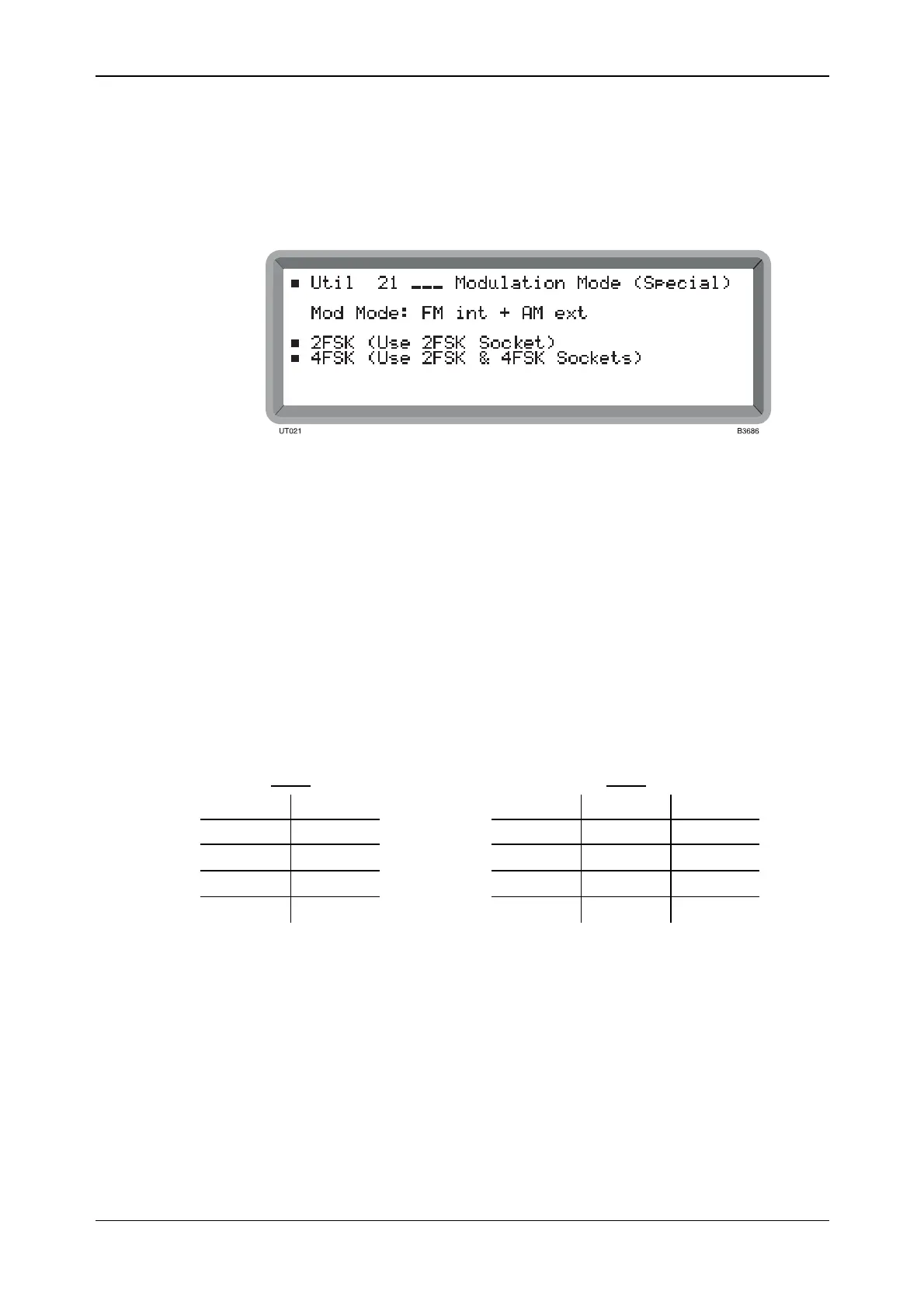
(1) Select the Util 21: Modulation Mode (Special) menu. This shows the currently selected
modulation mode against Mod Mode: (see Fig. 4-26).
Fig. 4-26 Modulation mode (special) menu
(2) Select the type of FSK. Either 2FSK or 4FSK is shown against Mod Mode.
(3) For 2FSK apply a TTL signal to the 2FSK socket. For 4FSK apply the signals to the 2FSK
and 4FSK sockets.
(4) Press [MOD] to return to the main screen with FM Devn displayed. Enter the required
deviation via the numerical key pad and terminate with the [Hz] or [kHz] key. If you
exceed the deviation limit for the current carrier frequency, the limit defaults to its
maximum value for the current carrier frequency range; see the deviation range table under
‘Frequency modulation’ in ‘Performance data’, Chapter 1.
(5) Either 2FSK Ext or 4FSK Ext is shown in the modulation source field. Note that for FSK
operation pressing [MOD SOURCE] has no effect on the instrument.
(6) If FSK is turned OFF no frequency shift is applied to the carrier.
The frequency shifts produced by the applied data are as follows:
2FSK
4FSK
2FSK SHIFT 2FSK 4FSK SHIFT
1 +D 1 0 +D
0
−D
1 1 +D/3
0 1
−D/3
0 0
−D
Where D is the set deviation value.