OPTION 11 FAST PULSE AND HIGH POWER
Annex-B-9
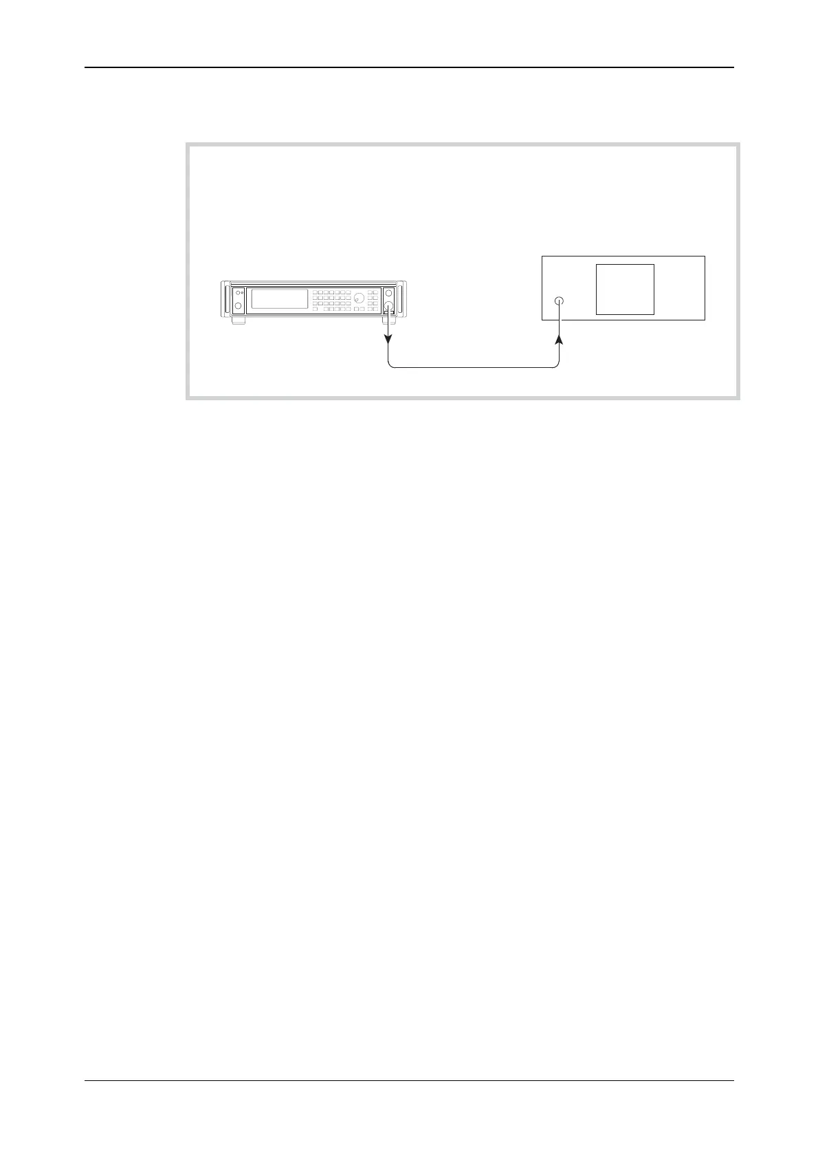
Test procedure
UUT
Spectrum analyzer
C5803
RF OUTPUT
RF INPUT
Fig. B-6 Carrier harmonics test set-up
(1) Press CAL on the spectrum analyzer.
(2) Connect the test equipment as shown in Fig. B-6.
(3) On the UUT set:
[CARR FREQ] 10 [kHz]
[RF LEVEL] −4 [dB]
(4) Measure the level of the second and third harmonics on the spectrum analyzer at each of the
carrier frequencies shown in Table B-8.
(5) Set the UUT RF level to +7 dBm and repeat (4) using Table B-9.
(6) Set the UUT RF level to +13 dBm and repeat (4) using Table B-10.
(7) Set the UUT RF level to +19 dBm and repeat (4) using Table B-11.
Pulse modulation
Specification
Carrier frequency range: 100 kHz to 2.51 GHz (usable to 9 kHz).
RF level range: Maximum guaranteed output is reduced by 3 dB when pulse
modulation is selected.
RF level accuracy:
Additional temperature coefficient ±0.01 dB/
°C when pulse modulation
is enabled.
On/off ratio: >80 dB below 1.2 GHz.
>70 dB below 2.1 GHz.
>65 dB above 2.1 GHz.
Rise and fall time: Less than 20 ns (typically 10 ns).