Quick Installation Guide Ensemble Epaq Hardware Manual
Quick Installation Guide
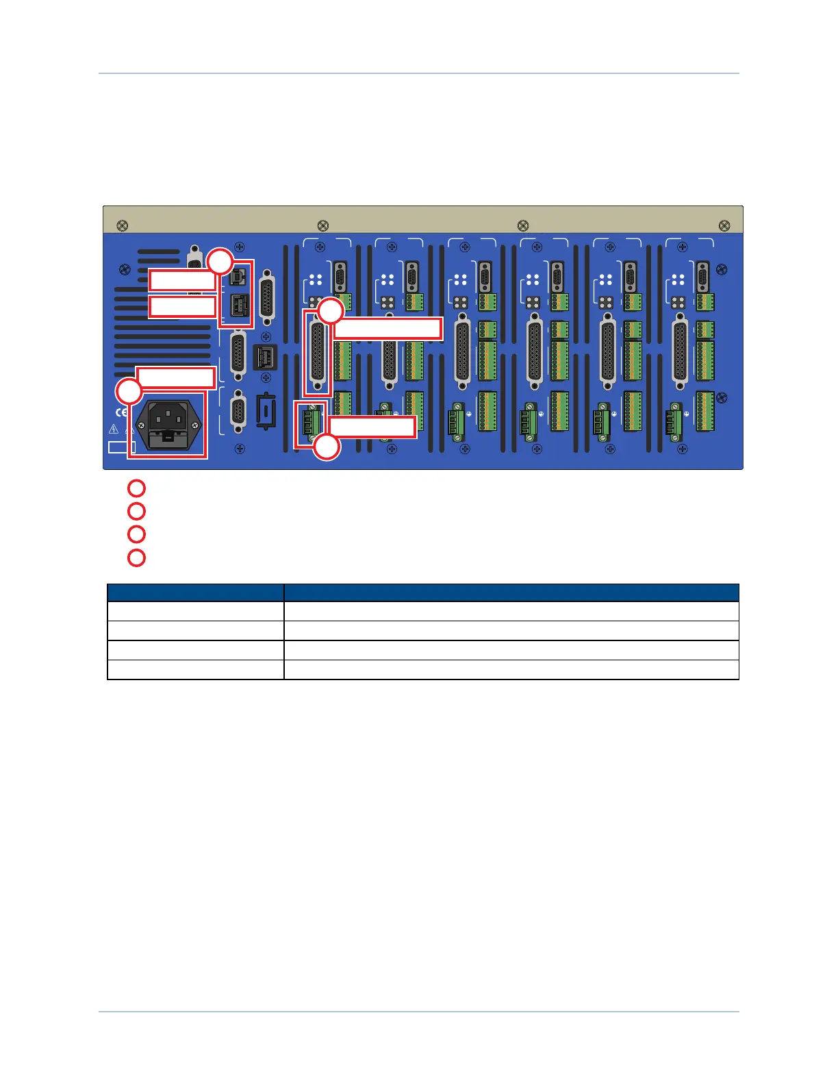
This chapter describes the order in which connections and settings should typically be made to the Epaq.
There are four standard connections that must be made to the Epaq.
USB
GPIB
ESTOP
EXT DRIVE
J100
ENET
JOY-
STICK
RS232
AXIS 1
BRAKE PWR
+5V/GND
AUX ENC
AIN/AOUT
OPTO-IN
FEEDBACK
MOTOR
OPTO-
OUT
ENA
CTL
MRK
1
4
1
1
4
10
1
A
B
C
10
IN POS
AXIS 2
BRAKE PWR
+5V/GND
AUX ENC
AIN/AOUT
OPTO-IN
FEEDBACK
MOTOR
OPTO-
OUT
ENA
CTL
MRK
1
4
1
1
4
10
1
A
B
C
10
IN POS
AXIS 3
BRAKE PWR
+5V/GND
AUX ENC
AIN/AOUT
OPTO-IN
FEEDBACK
MOTOR
OPTO-
OUT
ENA
CTL
MRK
1
4
1
1
4
10
1
A
B
C
10
IN POS
AXIS 4
BRAKE PWR
+5V/GND
AUX ENC
AIN/AOUT
OPTO-IN
FEEDBACK
MOTOR
OPTO-
OUT
ENA
CTL
MRK
1
4
1
1
4
10
1
A
B
C
10
IN POS
AXIS 5
BRAKE PWR
+5V/GND
AUX ENC
AIN/AOUT
OPTO-IN
FEEDBACK
MOTOR
OPTO-
OUT
ENA
CTL
MRK
1
4
1
1
4
10
1
A
B
C
10
IN POS
AXIS 6
BRAKE PWR
+5V/GND
AUX ENC
AIN/AOUT
OPTO-IN
FEEDBACK
MOTOR
OPTO-
OUT
ENA
CTL
MRK
1
4
1
1
4
10
1
A
B
C
10
IN POS
Motor Power
Motor Feedback
USB
Ethernet
4
2
3
From the Motor to the Motor Power input
3
From the Motor to the Motor Feedback input (depending on the type of motor).
4
From the power source to the AC Power input
1
From the PC to the USB or Ethernet input
2
AC Power
1
Topic Section
ACPower Section 2.1.1. ACPower Connections
PCCommunication Section 2.5. Communicating with the Epaq
Motor Power Section 2.2. Motor Output Connections
Motor Feedback Section 2.3. Motor Feedback Connections
Figure 1: Quick Start Connections
www.aerotech.com xiii