-IO Expansion Board Ensemble Epaq Hardware Manual
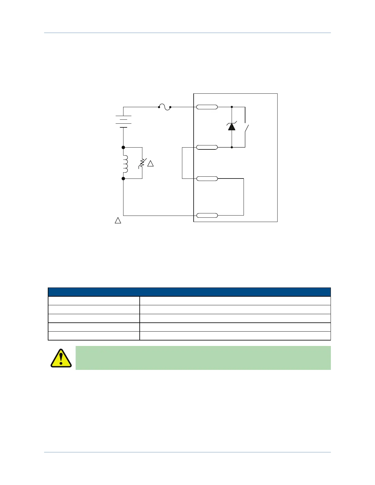
Figure 3-5 is an example of a 24 VDC Brake connected to the Brake Power Supply connector. The user must
connect [Motor Feedback connector pin 13] to [Motor Feedback connector pin 25]. In this case, the Motor
Feedback connector would function as an interlock to prevent the brake from releasing if the Motor Feedback
connector is not connected.
EPAQ
PS710A-1ASK
1N5369
1A
BRAKE
CONNECTOR PS-
PIN-2
FEEDBACK
CONNECTOR
PIN-13
FEEDBACK
CONNECTOR
PIN-25
BRAKE
CONNECTOR PS+
PIN-1
24 VDC
BRAKE
+
-
VARISTOR: AEROTECH P/N ECR180
HARRIS P/N V33ZA1
1
1
Figure 3-5: Brake Connected to Brake Power Supply connector
3.2.1. Solid State Relay Specifications
The user must verify that the application will be within the specifications of the Brake output.
Table 3-6: Relay Specifications
Solid State Relay Rating (M36), Aerotech PN. ECS1074
Operating Voltage 24 VDC(typical) / 48 VDC (max)
Maximum Current 0.5 Amps
Maximum Power 560 mW
Output Resistance 0.1 ohm (Typical)
Turn-On/Turn-Off Time < 3 mSec. (with 500 ohm load at 5 VDC)
W A R N I N G : Do not exceed the maximum specifications.
www.aerotech.com Chapter 3 61