Ensemble Epaq Hardware Manual -IO Expansion Board
3.7. Auxiliary Encoder Channel/PSO Output
The auxiliary encoder interface accepts a 5 VDC RS-422 differential quadrature line driver signal. It accepts
a 10 MHz (max) encoder signal frequency (25 nsec minimum edge separation), producing 40 million counts
per second, after times four (x4) quadrature decoding.
This encoder channel can be used as an input for master/slave operation (handwheel) or for dual feedback
systems. The auxiliary encoder interface does not support analog encoders and cannot be used as an input
for the -MXH or -MXU option.
The auxiliary encoder channel can also be used to echo the standard encoder signals or as the PSO output.
Configuring the PSO hardware will automatically configure this encoder channel as an output (refer to
Section 3.7.1.) and will remove the 180 ohm terminator resistors.
N O T E : Use the EncoderDivider parameter to configure the bi-directional encoder interface on the aux-
iliary I/O connector. The EncoderDivider parameter converts the auxiliary encoder interface to an output
and defines a divisor for the encoder echo. Refer to the EnsembleHelp file for more information.
N O T E : You cannot echo the standard encoder signals on the Epaq with the -MXU option.
DANGER!
High Voltage
GPIB
J100
RS232
AXIS 1
BRAKE PWR
+5V/GND
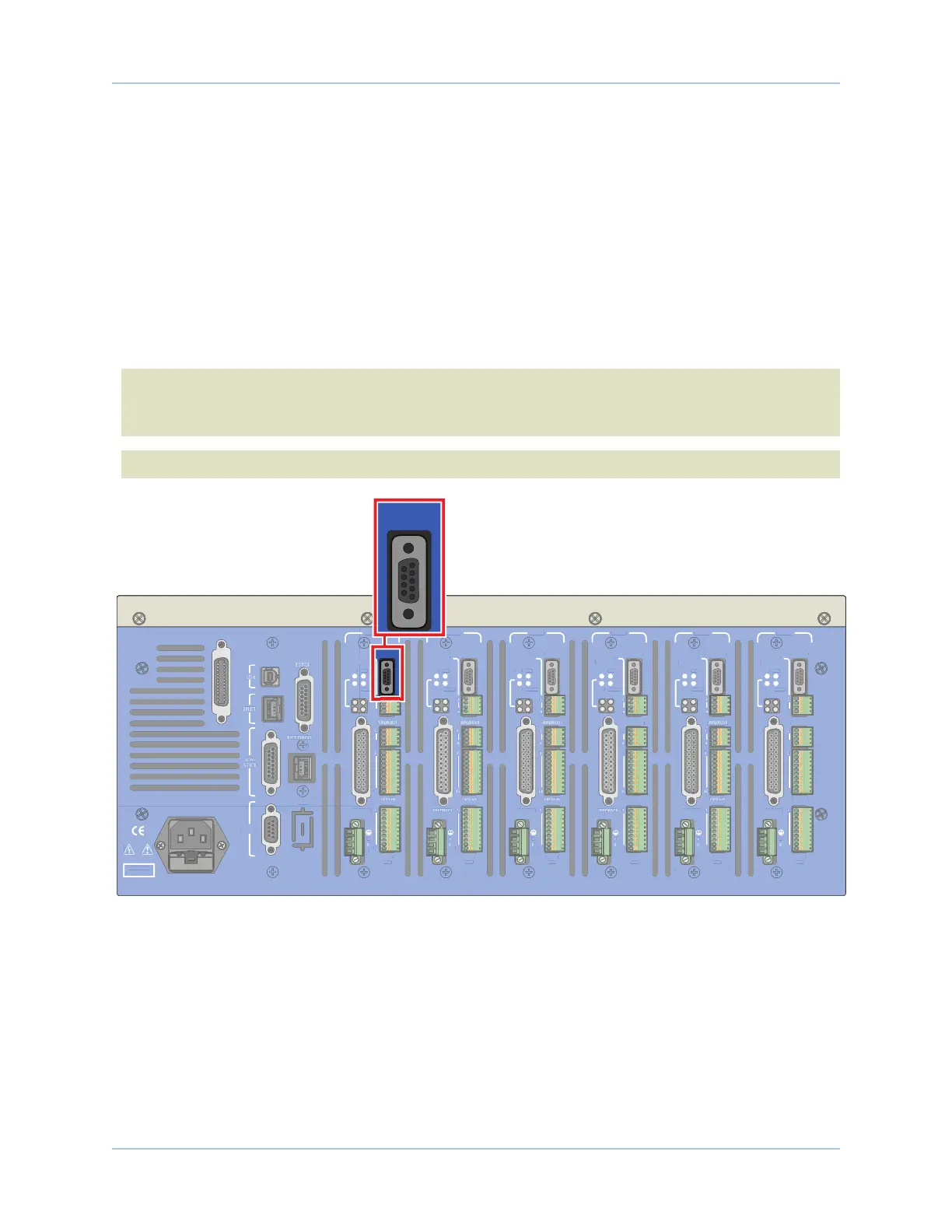
AUX ENC
FEEDBACK
MOTOR
OPTO-
OUT
ENA
CTL
MRK
1
4
1
1
4
10
1
A
B
C
10
IN POS
AXIS 2
BRAKE PWR
+5V/GND
AUX ENC
MOTOR
OPTO-
OUT
ENA
CTL
MRK
B
C
10
IN POS
AXIS 3
BRAKE PWR
+5V/GND
AUX ENC
FEEDBACK
MOTOR
OPTO-
OUT
ENA
CTL
MRK
A
B
C
10
IN POS
AXIS 4
BRAKE PWR
+5V/GND
AUX ENC
AIN/AOUT
OPTO-IN
MOTOR
OPTO-
OUT
ENA
CTL
MRK
B
C
10
IN POS
AXIS 5
BRAKE PWR
+5V/GND
AUX ENC
FEEDBACK
MOTOR
OPTO-
OUT
ENA
CTL
MRK
B
C
10
IN POS
AXIS 6
BRAKE PWR
+5V/GND
AUX ENC
AIN/AOUT
OPTO-IN
FEEDBACK
MOTOR
OPTO-
OUT
ENA
CTL
MRK
1
4
1
1
4
10
1
A
B
C
10
IN POS
Figure 3-13: Connector and Pin Locations
70 Chapter 3 www.aerotech.com