Ensemble Epaq Hardware Manual Installation and Configuration
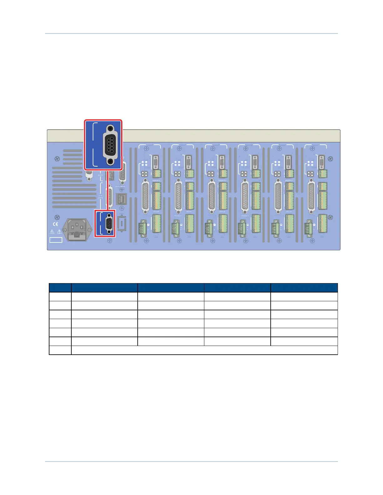
2.5.3. RS-232 Interface
Connecting the RS-232 port to a user’s PC requires a standard 9-pin cable (not a null modem). If the /RS232-
1 option has been purchased, an additional RS-232 port will be located at the J100 connector. The additional
RS-232 port will be identical in form and function to the standard RS-232 port.
This interface is also jumper configurable for RS-422 or RS-485 communication; refer to the Figure 2-33 for
jumper configuration.
DANGER!
High Voltage
GPIB
J100
RS232
AXIS 1
BRAKE PWR
+5V/GND
AUX ENC
FEEDBACK
MOTOR
OPTO-
OUT
ENA
CTL
MRK
1
4
1
1
4
10
1
A
B
C
10
IN POS
AXIS 2
BRAKE PWR
+5V/GND
AUX ENC
MOTOR
OPTO-
OUT
ENA
CTL
MRK
B
C
10
IN POS
AXIS 3
BRAKE PWR
+5V/GND
AUX ENC
FEEDBACK
MOTOR
OPTO-
OUT
ENA
CTL
MRK
A
B
C
10
IN POS
AXIS 4
BRAKE PWR
+5V/GND
AUX ENC
AIN/AOUT
OPTO-IN
MOTOR
OPTO-
OUT
ENA
CTL
MRK
B
C
10
IN POS
AXIS 5
BRAKE PWR
+5V/GND
AUX ENC
FEEDBACK
MOTOR
OPTO-
OUT
ENA
CTL
MRK
B
C
10
IN POS
AXIS 6
BRAKE PWR
+5V/GND
AUX ENC
AIN/AOUT
OPTO-IN
FEEDBACK
MOTOR
OPTO-
OUT
ENA
CTL
MRK
1
4
1
1
4
10
1
A
B
C
10
IN POS
Figure 2-32: RS-232 Connector Location
Table 2-19: RS-232 Connector Pin Assignment
Pin # Label RS-232 Description RS-485 Description In/Out/Bi
1 +5V +5V Power +5V Power Output
2 TX/TX1+ Transmit Transmit + Output
3 RX/RX1+ Receive Receive + Bidirectional
4 TX1- N/A Transmit - Output
5 Common Signal Common Signal Common N/A
6 RX1- N/A Receive - Bidirectional
7-9 Reserved/Do Not Connect
52 Chapter 2 www.aerotech.com


 To Next Page