Introduction Ensemble Epaq Hardware Manual
Chapter 1: Introduction
Aerotech’s Epaq is a 3U height, 19” wide, rack-mountable, intelligent drive chassis, capable of powering up
to nine axes of motion. Six axes of motion control are available in one integrated, stand-alone package and
can be expanded to nine axes of motion control externally. This flexible configuration style allows users to
mix and match drive types (linear versus PWM, brush or brushless, stepper, etc.) within the same
positioning system using a common programming and control platform. Multiple Epaqs can be controlled
from one Windows PC through Ethernet or USB. Optional on-board encoder interpolation offers the user
programmable axis resolution (assuming a sine-wave encoder input signal), including the ability to change
interpolation (multiplication) values through software.
DANGER!
High Voltage
USB
GPIB
ESTOP
EXT DRIVE
J100
ENET
JOY-
STICK
RS232
AXIS 1
BRAKE PWR
+5V/GND
AUX ENC
AIN/AOUT
OPTO-IN
FEEDBACK
MOTOR
OPTO-
OUT
ENA
CTL
MRK
1
4
1
1
4
10
1
A
B
C
10
IN POS
AXIS 2
BRAKE PWR
+5V/GND
AUX ENC
AIN/AOUT
OPTO-IN
FEEDBACK
MOTOR
OPTO-
OUT
ENA
CTL
MRK
1
4
1
1
4
10
1
A
B
C
10
IN POS
AXIS 3
BRAKE PWR
+5V/GND
AUX ENC
AIN/AOUT
OPTO-IN
FEEDBACK
MOTOR
OPTO-
OUT
ENA
CTL
MRK
1
4
1
1
4
10
1
A
B
C
10
IN POS
AXIS 4
BRAKE PWR
+5V/GND
AUX ENC
AIN/AOUT
OPTO-IN
FEEDBACK
MOTOR
OPTO-
OUT
ENA
CTL
MRK
1
4
1
1
4
10
1
A
B
C
10
IN POS
AXIS 5
BRAKE PWR
+5V/GND
AUX ENC
AIN/AOUT
OPTO-IN
FEEDBACK
MOTOR
OPTO-
OUT
ENA
CTL
MRK
1
4
1
1
4
10
1
A
B
C
10
IN POS
AXIS 6
BRAKE PWR
+5V/GND
AUX ENC
AIN/AOUT
OPTO-IN
FEEDBACK
MOTOR
OPTO-
OUT
ENA
CTL
MRK
1
4
1
1
4
10
1
A
B
C
10
IN POS
1
2
3
4
9
10
11
12
13
14
15
16
5
6
7
8
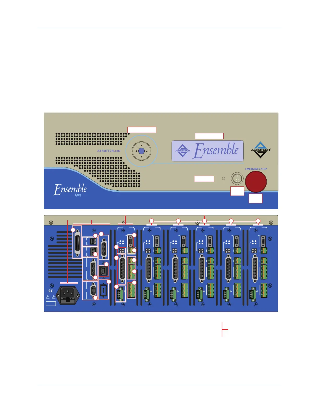
Control Board
1. USB connector
2. Ethernet connector
3. Joystick 15-pin D-style connector
4. RS-232 9-pin D-style connector
Options
5. GPIB IEEE-488 Connector (talker/listener)
6. ESTOP (Emergency Stop) 9-pin D-style connector
7. External Drive Connector
8. J100 / additional optional RS-232 connector
Control Board
and Options
Axis 1 Axes 2 through 6 (Optional)
Axis 1
9. LED Status Display
10. Feedback 25-pin D-style connector
11. Motor Connector (terminal block)
Axis 1 I/O (standard on Axis 1)
12. Auxiliary Encoder 9-pin D-style connector
13. Brake Power (terminal block)
14. Analog Input/Output (terminal block)
15. Opto-Isolator Input (terminal block)
16. Opto-Isolator Output (terminal block)
Additional Axes
17. Axis 2
18. Axis 3
19. Axis 4
20. Axis 5
21. Axis 6
In this example:
This Epaq is configured for 5 axes
Axis 5 does not support the -IO option
Axes 2 through 6 are optional.
The I/O board is optional on axes
2 through 6.
AC Power
Input
17 18 19 20 21
POWER
Directional Keypad
LCD Screen
ESTOP
Button
Power
Switch
Power LED
Figure 1-1: Epaq Networked Digital Drive
www.aerotech.com Chapter 1 1

 Loading...