Maintenance Ensemble Epaq Hardware Manual
5.3. Integrated Axis Control Boards (Amplifier)
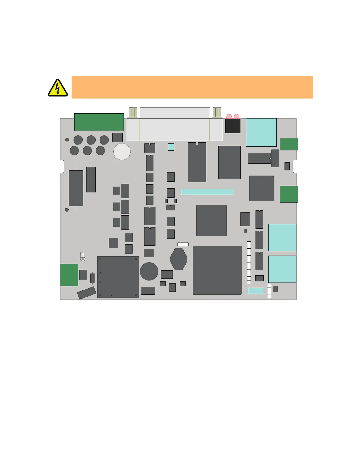
Figure 5-3 and Figure 5-4 highlight the important components located on the MPand MLaxis control boards.
Refer to Table 5-5 for fuse replacement information.
D A N G E R : Always disconnect the Mains power connection before opening the Ensemble
Epaq chassis.
Drawing Number: 690D1622
DS1
DS2
Test Points
321
Test Points
4
5
6
7
8
9
10
11
12
13
14
15
F2
5ASB
TB102
(MOTOR POWER)
TB103
2 A PICO
F1
J103
(MOTOR FEEDBACK)
TB105
TB104
16
17
18
19
Test Points
Figure 5-3: MP Board Assembly
www.aerotech.com Chapter 5 83