Ensemble Epaq Hardware Manual Installation and Configuration
2.3.1.3. Encoder Phasing
Incorrect encoder polarity will cause the system to fault when enabled or when a move command is issued.
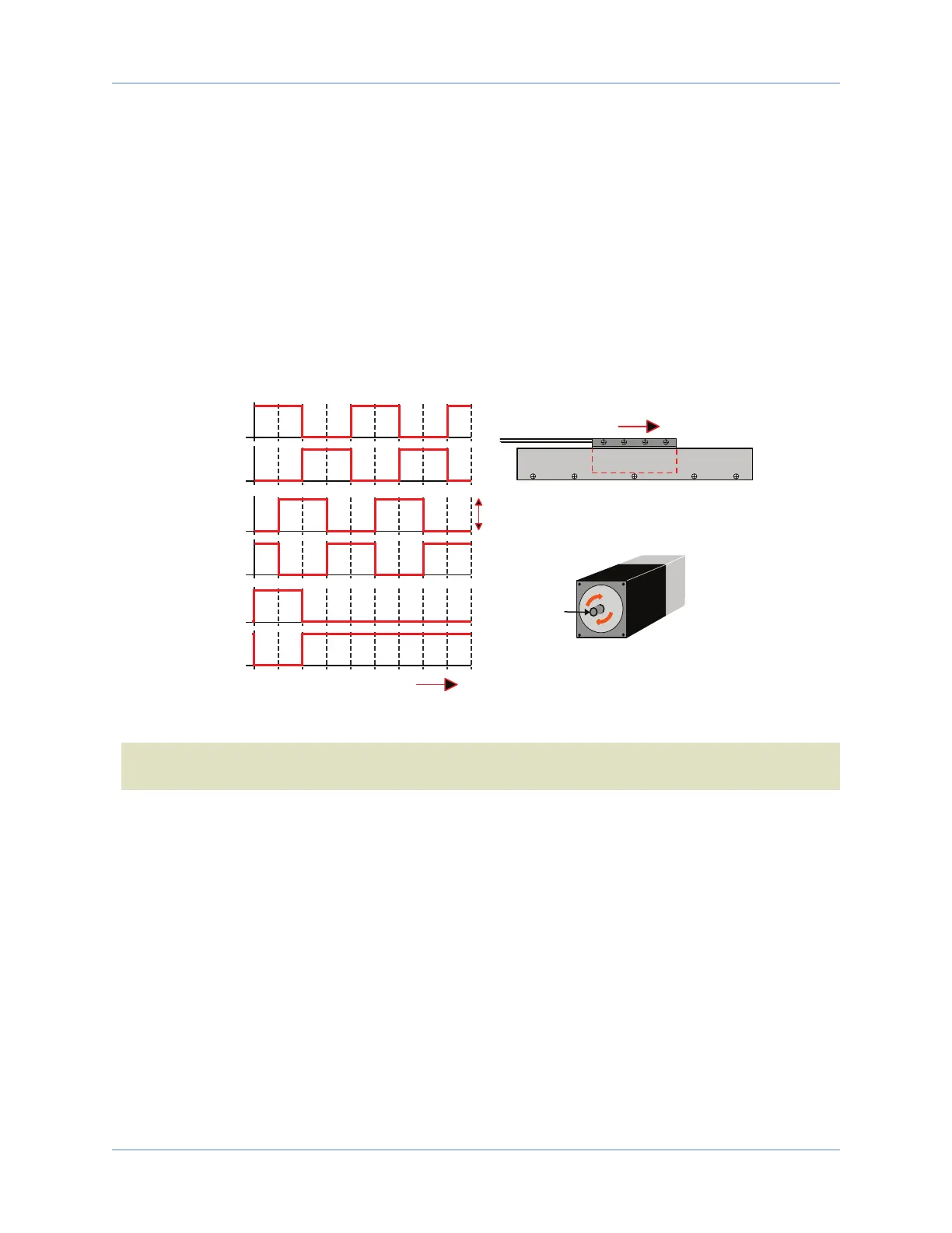
Figure 2-19 illustrates the proper encoder phasing for clockwise motor rotation (or positive forcer movement
for linear motors). To verify, move the motor by hand in the CW (positive) direction while observing the
position of the encoder in the diagnostics display (see Figure 2-20). The MotorVerification.ab program can be
used if the motor can not be moved by hand. If the program causes the Position Feedback to count more
negative, swap the connections to the controllers SIN and the SIN-N encoder inputs.
However, if this axis is configured for dual loop with two feedback devices (one for position and one for
velocity feedback), invert the sign of only the parameter associated with the incorrectly phased feedback
device. For dual loop systems, the velocity feedback encoder is displayed in “Auxiliary Encoder Input” in the
Diagnostic display.
SIN
SIN-N
COS
COS-N
MRK
MRK-N
Positive MOVE (Clockwise)
Forcer Wires
ForcerMagnet Track
Motor Mounting
Flange (Front View)
Motor Shaft
CW Rotation
(Positive Direction)
LINEAR MOTOR
ROTARY MOTOR
Positive MOVE
(Clockwise)
0° 90° 180° 270° 360° 450° 540° 630° 720° 810°
0° 90° 180° 270° 360° 450° 540° 630° 720° 810°
0° 90° 180° 270° 360° 450° 540° 630° 720° 810°
1V
pk-pk
Figure 2-19: Encoder Phasing Reference Diagram (Standard)
N O T E :Encoder manufacturers may refer to the encoder signals as A, B, and Z. The proper phase rela-
tionship between signals is shown in Figure 2-19.
38 Chapter 2 www.aerotech.com