Ensemble Epaq Hardware Manual -IO Expansion Board
Table 3-5: Motor Feedback Connector Brake Output Connector Pin Assignment
Pin# Description In/Out/Bi
13 Optional Brake - Output Output
25 Optional Brake +Output Output
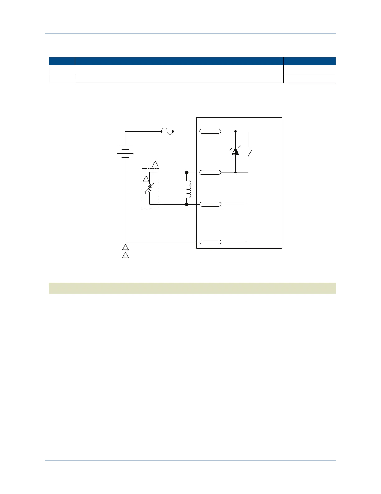
Figure 3-4 is an example of a +24 VDC Brake connected to the Motor Feedback connector. In this example
the external +24 VDC power source is connected to the Brake Power Supply connector.
EPAQ
PS710A-1ASK
1N5369
1A
BRAKE
CONNECTOR PS-
PIN-2
FEEDBACK
CONNECTOR
PIN-13
FEEDBACK
CONNECTOR
PIN-25
BRAKE
CONNECTOR PS+
PIN-1
24 VDC
BRAKE
+
-
NOISE SUPPRESSION CIRCUIT
1
2
1
VARISTOR: AEROTECH P/N ECR180
HARRIS P/N V33ZA1
2
Figure 3-4: Brake Connected to the Feedback Connector
N O T E : The user is responsible for providing fuse protection for the brake circuit.
60 Chapter 3 www.aerotech.com