-IO Expansion Board Ensemble Epaq Hardware Manual
3.5. Opto-Isolated Inputs
These opto-isolated inputs use a PS2806-4 device and are configured for 5-24 volt input levels. The inputs
may be connected to current sourcing or current sinking devices, as shown in Figure 3-9 and Figure 3-10.
See Section 2.3.4. for opto-isolated EOT limits.
Inputs 0-3 and inputs 4-7 have separate common inputs, pin 1 and pin 10, respectively. Each 4-bit bank of
inputs must be connected in the same configuration (sinking or sourcing).
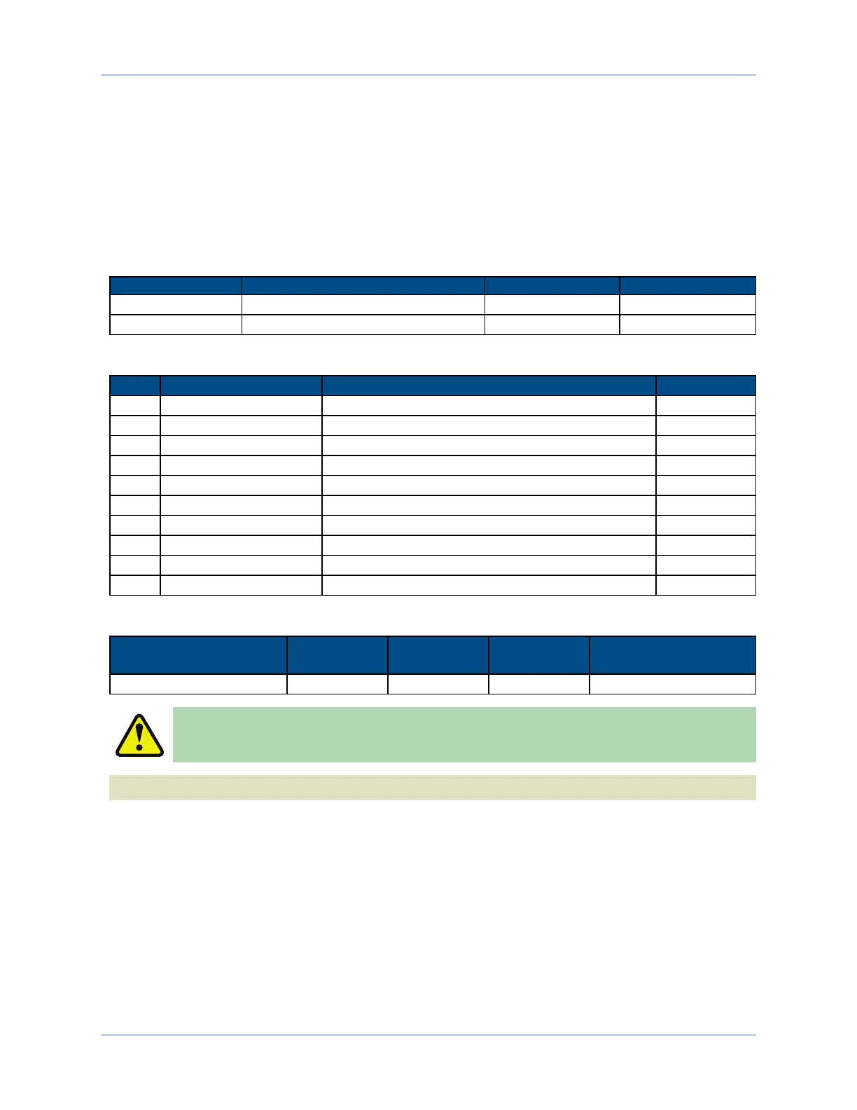
Table 3-11: Digital Input Specifications
Input Voltage Approximate Input Current Turn On Time Turn Off Time
+5 V 1 mA 200 usec 2000 usec
+24 V 6 mA 4 usec 1500 usec
Table 3-12: Port 1 Opto-Isolated Input Connector Pin Assignment
Pin# Label Description In/Out/Bi
1 C (0-3) Input Common for inputs 0 - 3 Input
2 0 Input 0 (Optically-Isolated) Input
3 1 Input 1 (Optically-Isolated) Input
4 2 Input 2 (Optically-Isolated) Input
5 3 Input 3 (Optically-Isolated) Input
6 4 Input 4 (Optically-Isolated) Input
7 5 Input 5 (Optically-Isolated) Input
8 6 Input 6 (Optically-Isolated) Input
9 7 Input 7 (Optically-Isolated) Input
10 C (4-7) Input Common for inputs 4 - 7 Input
Table 3-13: Opto-Isolated Input Mating Connector
Type Aerotech P/N Phoenix P/N
Tightening
Torque (Nm) Wire Size: mm
2
[AWG]
10-Pin Terminal Block ECK01294 1881406 N/A 0.5 - 0.080 [20-28]
W A R N I N G : Opto-isolated inputs and outputs should not be powered by the user output
power. Doing so would compromise the isolation provided by the opto-isolator.
N O T E : Inputs must be connected in the all sourcing or all sinking configuration.
www.aerotech.com Chapter 3 65