Installation and Configuration Ensemble Epaq Hardware Manual
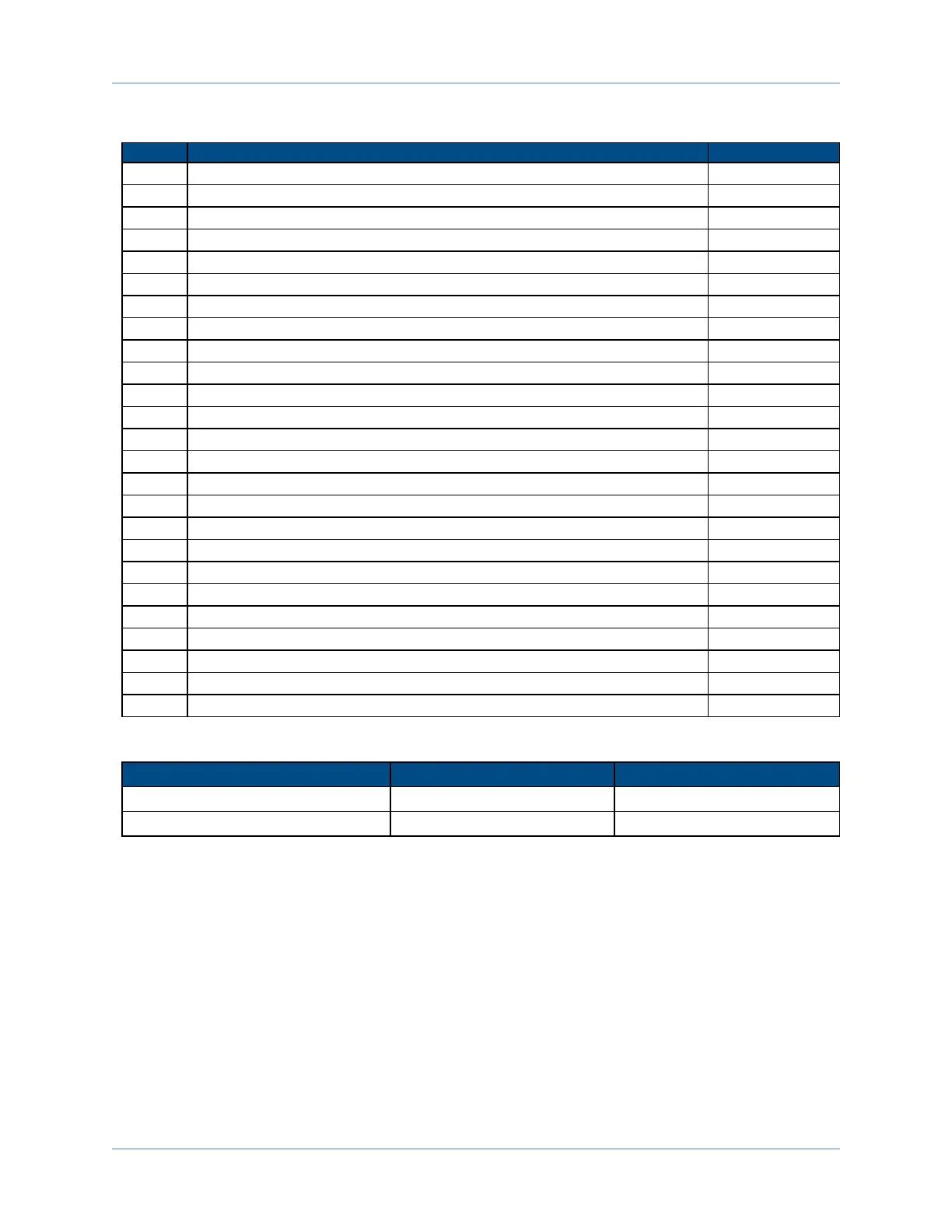
Table 2-8: Motor Feedback Connector Pin Assignment
Pin# Description In/Out/Bi
1 Chassis Frame Ground N/A
2 Motor Over Temperature Thermistor Input
3 +5V Power for Encoder (500 mAmax) Output
4 Reserved N/A
5 Hall-Effect Sensor B (brushless motors only) Input
6 Encoder Marker Reference Pulse - Input
7 Encoder Marker Reference Pulse + Input
8 Analog Input 0 - Input
9 Reserved N/A
10 Hall-Effect Sensor A (brushless motors only) Input
11 Hall-Effect Sensor C (brushless motors only) Input
12 Clockwise End of Travel Limit Input
13 Optional Brake - Output Output
14 Encoder Cosine + Input
15 Encoder Cosine - Input
16 +5V Power for Limit Switches (500 mAmax) Output
17 Encoder Sine + Input
18 Encoder Sine - Input
19 Analog Input 0 + Input
20 Signal Common for Limit Switches N/A
21 Signal Common for Encoder N/A
22 Home Switch Input Input
23 Encoder Fault Input Input
24 Counterclockwise End of Travel Limit Input
25 Optional Brake +Output Output
Table 2-9: Motor Feedback Mating Connector
Aerotech P/N ThirdParty P/N
Connector ECK00101 Cinch P/N DB25P
Backshell ECK00656 Amphenol P/N 17-1726-2
www.aerotech.com Chapter 2 33