Installation and Configuration Ensemble Epaq Hardware Manual
2.5.2. Ethernet Interface
The Ethernet interface is the high-speed communications media to the Epaq. Command and configuration
information is sent through this interface.
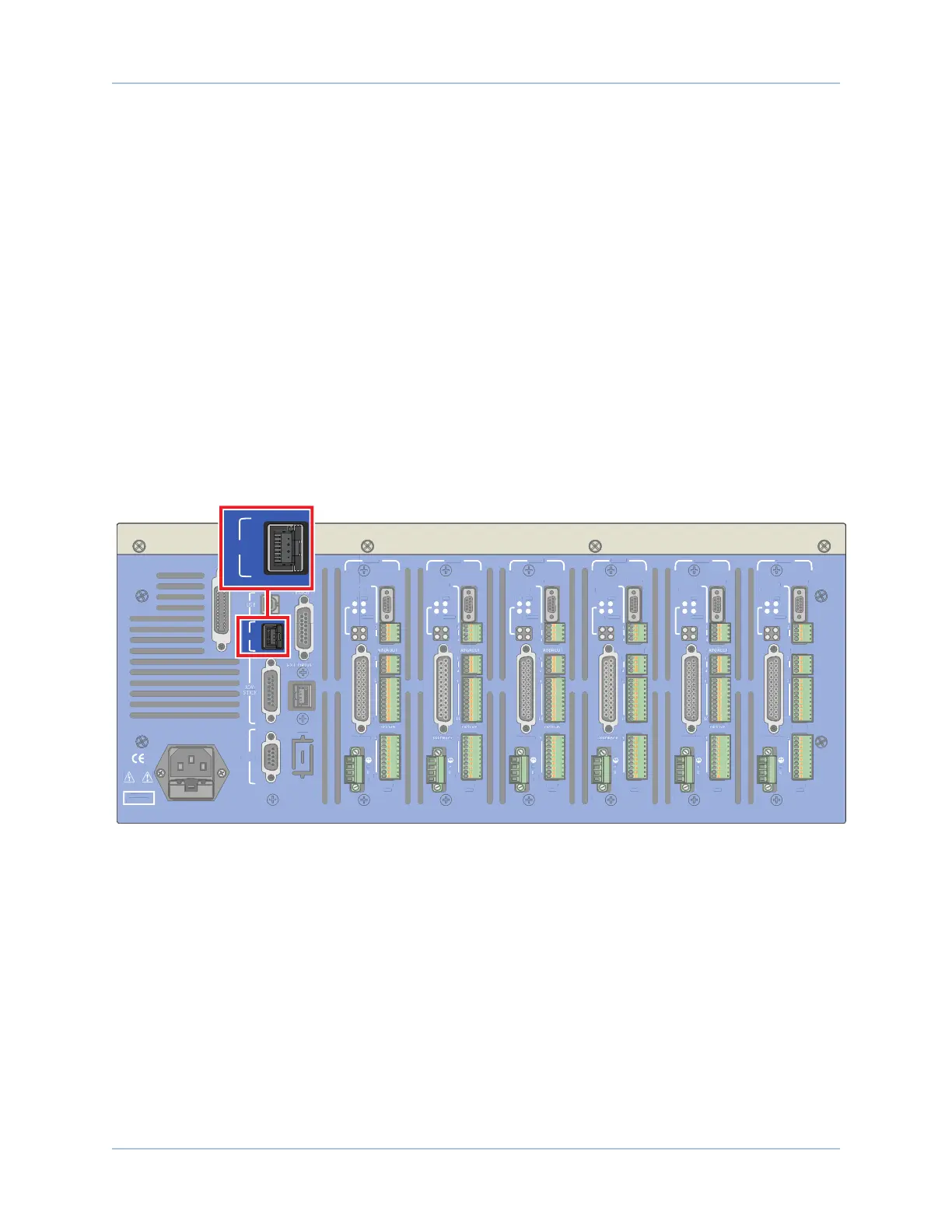
The Ethernet connection is established through the RJ-45 connector labeled ENET on the back panel of the
Epaq. Connection is accomplished by one of these two methods:
Method 1: Directly connect to the PC with an RJ-45 crossover cable.
Method 2: Connect through a network with a standard RJ-45 cable.
Method 1 is the most secure because is guarantees that the only members of the network are the Epaq and
the PC. This type of connection is not feasible unless the PC has two Ethernet cards. If the PC cannot be
connected to an external network, Aerotech recommends Method 2.
Method 2 is a more typical configuration. The network can be a local network (the PC and Epaq are
connected through a hub or switch) or remote (the devices are connected through a router). When connecting
to a remote network, a crossover cable cannot be used; instead, there must be a hub, switch, or router
interface between the PC and the Epaq.
DANGER!
High Voltage
GPIB
J100
ENET
RS232
AXIS 1
BRAKE PWR
+5V/GND
AUX ENC
FEEDBACK
MOTOR
OPTO-
OUT
ENA
CTL
MRK
1
4
1
1
4
10
1
A
B
C
10
IN POS
AXIS 2
BRAKE PWR
+5V/GND
AUX ENC
MOTOR
OPTO-
OUT
ENA
CTL
MRK
B
C
10
IN POS
AXIS 3
BRAKE PWR
+5V/GND
AUX ENC
FEEDBACK
MOTOR
OPTO-
OUT
ENA
CTL
MRK
A
B
C
10
IN POS
AXIS 4
BRAKE PWR
+5V/GND
AUX ENC
AIN/AOUT
OPTO-IN
MOTOR
OPTO-
OUT
ENA
CTL
MRK
B
C
10
IN POS
AXIS 5
BRAKE PWR
+5V/GND
AUX ENC
FEEDBACK
MOTOR
OPTO-
OUT
ENA
CTL
MRK
B
C
10
IN POS
AXIS 6
BRAKE PWR
+5V/GND
AUX ENC
AIN/AOUT
OPTO-IN
FEEDBACK
MOTOR
OPTO-
OUT
ENA
CTL
MRK
1
4
1
1
4
10
1
A
B
C
10
IN POS
Figure 2-31: Ethernet Connector Location
www.aerotech.com Chapter 2 51