Installation and Configuration Ensemble Epaq Hardware Manual
2.2.1.2. Unpowered Motor and Feedback Phasing
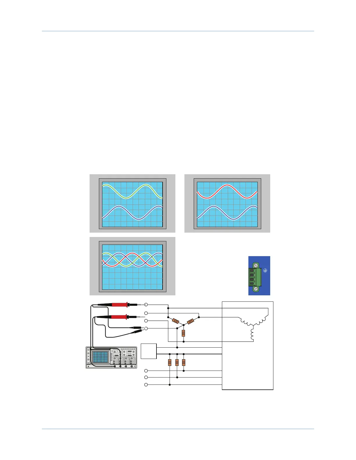
Disconnect the motor from the controller and connect the motor in the test configuration shown in Figure 2-7.
This method will require a two-channel oscilloscope, a 5V power supply, and six resistors (10,000 ohm, 1/4
watt). All measurements should be made with the probe common of each channel of the oscilloscope
connected to a neutral reference test point (TP4, shown in Figure 2-7).
To determine the relative phasing/order of the three motor lead signals in relation to each other, connect
channel 1 of the oscilloscope to TP1. Connect channel 2 to TP2 and move the motor in the positive direction
(CW) by hand. Note the peak of the sine wave signal of channel 1 in comparison to the peak of the sine wave
signal of channel 2. Next, disconnect channel 2 from TP2 and reconnect it to TP3 and again move the motor
in the positive direction. Note the peak of the sine wave signal of channel 3 in comparison to the peak of the
sine wave signal of channel 1.
Aerotech phasing configuration expects ØC to be the lead signal (in time), ØB to follow it, and ØA to follow
ØB. This means that whichever signal has its sine wave peak farthest to the left should be designated as the
ØC signal.
TP5
TP4
COM
+5V
COM
+5V
10K OHM
TYP
"Wye"
Configuration
10K OHM
TYP
Motor Lead 3
= ØA
Motor Lead 1 = ØB
Motor Lead 2
= ØC
Power Supply
TP3
TP2
TP1
TP6
TP7
Hall 1
Hall 2
Hall 3
CHANNEL 1
CHANNEL 2
Channel 1 at TP1 and Channel 2 at TP2
CH1
(TP1)
CH1
(TP1)
CH2
(TP2)
CH2
(TP3)
Channel 1 at TP1 and Channel 2 at TP3
In this example:
The peak of the sine wave signal at TP2 precedes the
peaks of the sine wave signals at TP1 and TP3. The peak
of the sine wave signal at TP1 precedes the peak of the
sine wave signals at TP3.
TP2 = Motor Lead 2 = ØC signal
TP1 = Motor Lead 1 = ØB signal
TP3 = Motor Lead 3 = ØA signal
After the phasing process is complete,
the ØA, ØB, and ØC signal motor leads
should be connected to their respective
Motor Outputs (A to A, B to B and C to C).
Signals Combined for Comparison
ØC ØB ØC ØBØA
MOTOR
A
B
C
Figure 2-7: Motor Phasing Oscilloscope Example
www.aerotech.com Chapter 2 25