Ensemble Epaq Hardware Manual Introduction
1.1. Electrical Specifications
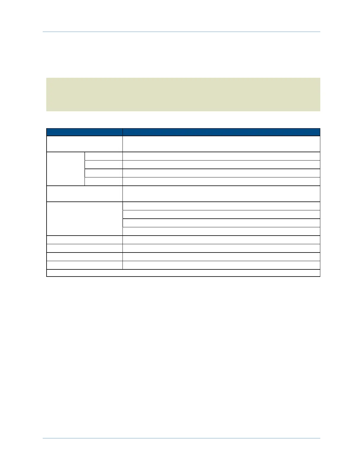
The electrical specifications for the Epaq drive chassis are listed in Table 1-3 and the electrical
specifications for the servo amplifiers in Table 1-4.
N O T E :Specifications represent the maximum capability of a feature. Other system constraints may res-
ult in significantly less performance. This is particularly applicable to the motor output specifications. The
motor output specifications are affected by the Bus supply, the number of axes that are operating at the
same time, the type of motion, the AC Line voltage, and motor requirements.
Table 1-3: Chassis Electrical Specifications
Description Specification
Bus Voltage Options * 40 VDC or 80 VDC at 600 W; 40 VDC or 80 VDC at 300 W [Factory
Configured]
ACPower 100 VAC 90 - 112 VAC, 50/60 Hz, 10 A maximum
115 VAC 103 - 127 VAC, 50/60 Hz, 10 A maximum
200 VAC 180 - 224 VAC, 50/60 Hz, 6 A maximum
230 VAC 207 - 254 VAC, 50/60 Hz, 5 A maximum
Auxiliary Power Outputs +5 V provided on all axis feedback connectors for encoder, Hall, and limit
power
Protection Fuse in AC power inlet (10 A, supplemental protection only)
Amplifier Output short circuit protection
Peak and RMS over current limit
Over Temperature shutdown
Isolation Opto and transformer isolation between control and power stages
Indicator (Power) Power switch contains a power-on indicator
Indicator (Enabled) Individual Amplifier LED’s indicates drive enabled state
Standards Conformity Designed to EN61010 / UL3101
*Bus power supplies of 24, 48, 54, and 90 VDC are obsolete as of September 2008.
8 Chapter 1 www.aerotech.com