Ensemble Epaq Hardware Manual Installation and Configuration
2.5. Communicating with the Epaq
Either USB or Ethernet can be used to connect any of the supplied software applications or a custom
application built with the supplied .NET library to the controller. Ethernet sockets are also available for
Modbus or general ASCII communication with another hardware device. RS-232 can be used for general
ASCII communication with another hardware device, but can not be used with the supplied software
applications.
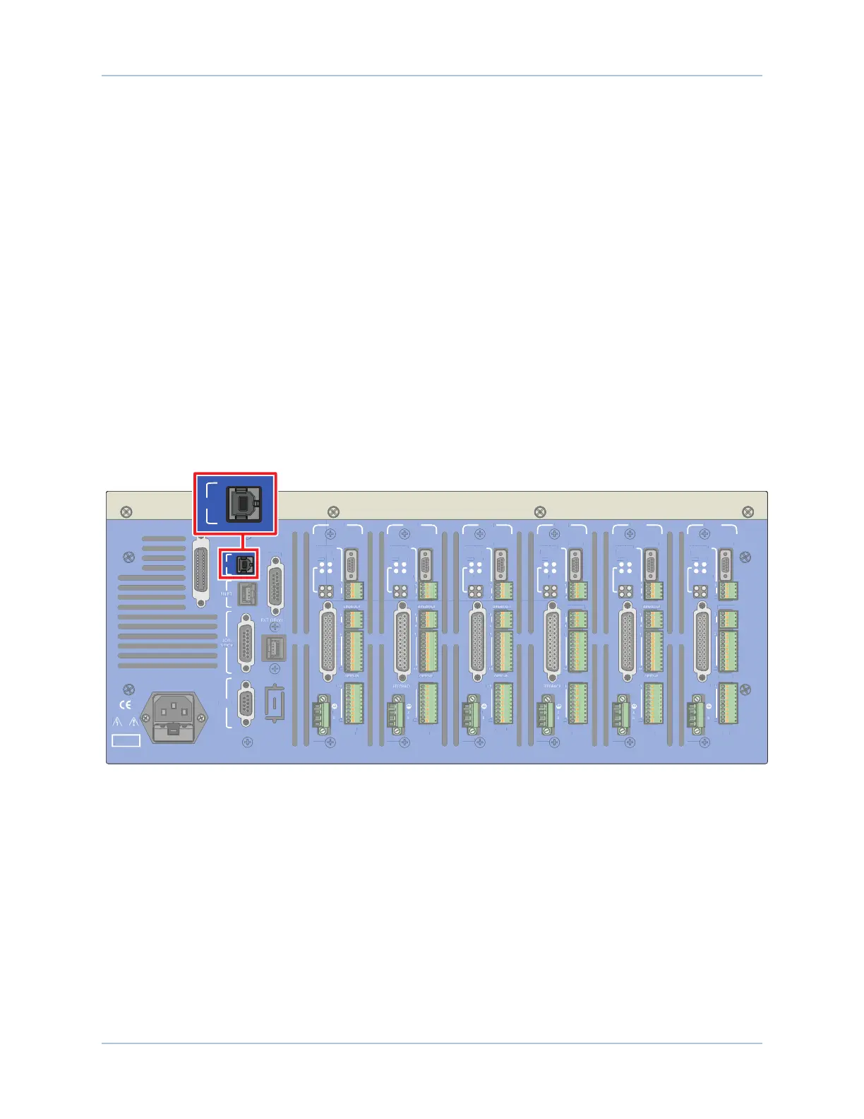
2.5.1. USB Interface
The USB connection is established through a Type B female connector labeled USB on the back panel of the
Epaq. This can be accomplished by one of these two methods:
Method 1: Directly connect to the PC with a standard USB cable. The cable connector type must be
Type A or Type B male depending on the PC, and Type B male on the Epaq.
Method 2: Connect through a USB hub. The cable connector type must be Type A or Type B male
depending on the hub, and Type B male on the Epaq.
Method 1 is the most commonly used. Method 2 is necessary only when the number of Epaqs to be
connected is larger than the number of available USB ports on the PC.
DANGER!
High Voltage
USB
GPIB
ESTOP
J100
RS232
AXIS 1
BRAKE PWR
+5V/GND
AUX ENC
FEEDBACK
MOTOR
OPTO-
OUT
ENA
CTL
MRK
1
4
1
1
4
10
1
A
B
C
10
IN POS
AXIS 2
BRAKE PWR
+5V/GND
AUX ENC
MOTOR
OPTO-
OUT
ENA
CTL
MRK
B
C
10
IN POS
AXIS 3
BRAKE PWR
+5V/GND
AUX ENC
FEEDBACK
MOTOR
OPTO-
OUT
ENA
CTL
MRK
A
B
C
10
IN POS
AXIS 4
BRAKE PWR
+5V/GND
AUX ENC
AIN/AOUT
OPTO-IN
MOTOR
OPTO-
OUT
ENA
CTL
MRK
B
C
10
IN POS
AXIS 5
BRAKE PWR
+5V/GND
AUX ENC
FEEDBACK
MOTOR
OPTO-
OUT
ENA
CTL
MRK
B
C
10
IN POS
AXIS 6
BRAKE PWR
+5V/GND
AUX ENC
AIN/AOUT
OPTO-IN
FEEDBACK
MOTOR
OPTO-
OUT
ENA
CTL
MRK
1
4
1
1
4
10
1
A
B
C
10
IN POS
Figure 2-30: USB Connector Location
50 Chapter 2 www.aerotech.com
 Loading...


