Ensemble Epaq Hardware Manual Installation and Configuration
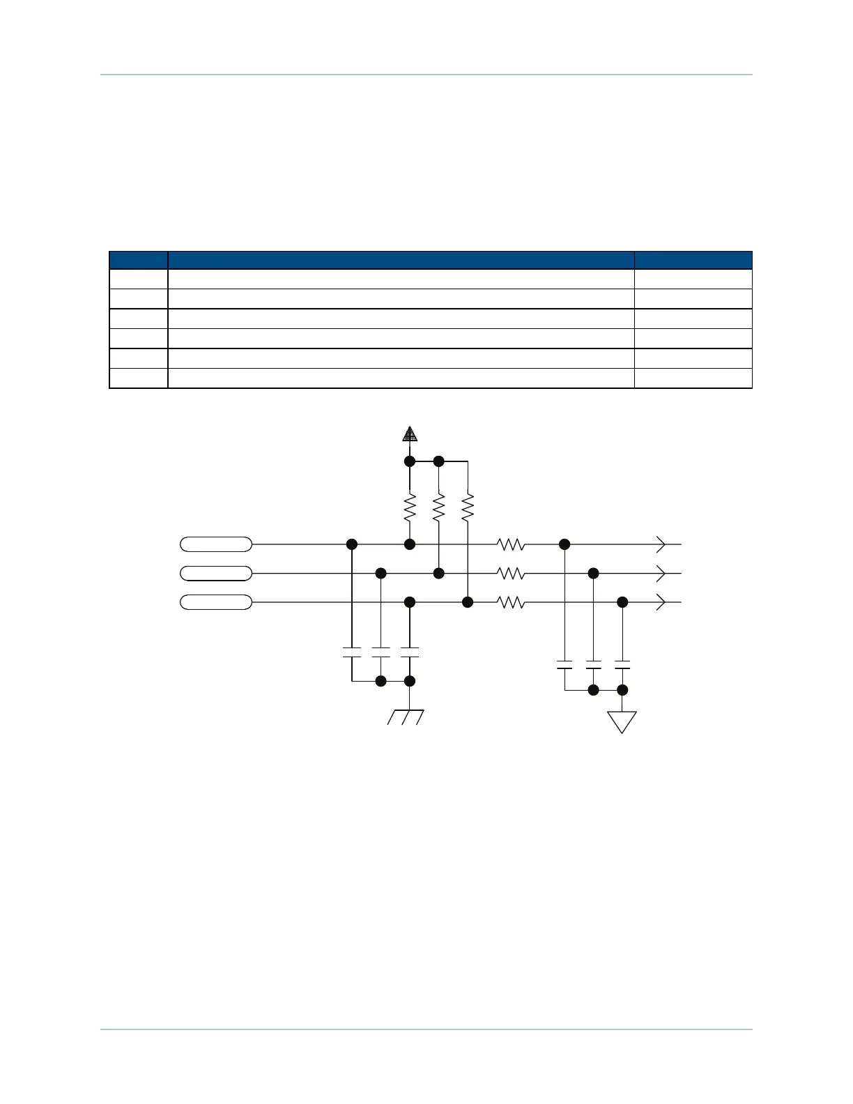
2.3.2. Hall-Effect Interface
The Hall-effect switch inputs are recommended for AC brushless motor commutation but not absolutely
required. The Hall-effect inputs accept 5-24 VDC level signals.
Refer to Section 2.2.1.1. for Hall-effect device phasing.
Table 2-12: Hall-Effect Feedback Interface Pin Assignment
Pin# Description In/Out/Bi
1 Chassis Frame Ground N/A
3 +5V Power for Encoder (500 mAmax) Output
5 Hall-Effect Sensor B (brushless motors only) Input
10 Hall-Effect Sensor A (brushless motors only) Input
11 Hall-Effect Sensor C (brushless motors only) Input
21 Signal Common for Encoder N/A
ENC+5V
HALL A
HALL B
HALL C
PIN-10
PIN-5
PIN-11
10K
10K
10K
10K
.001
.001
.001
.01UF
.01UF
.01UF
10K
10K
Figure 2-21: Hall-Effect Inputs
40 Chapter 2 www.aerotech.com

 Loading...