Ensemble Epaq Hardware Manual Installation and Configuration
2.1. Electrical Installation
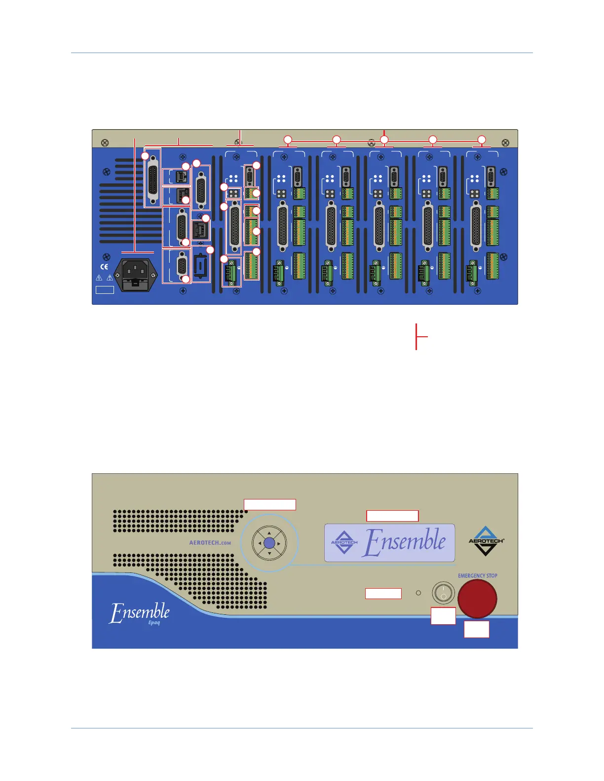
Motor, power, control and position feedback cable connections are made to the rear of the Epaq.
DANGER!
High Voltage
USB
GPIB
ESTOP
EXT DRIVE
J100
ENET
JOY-
STICK
RS232
AXIS 1
BRAKE PWR
+5V/GND
AUX ENC
AIN/AOUT
OPTO-IN
FEEDBACK
MOTOR
OPTO-
OUT
ENA
CTL
MRK
1
4
1
1
4
10
1
A
B
C
10
IN POS
AXIS 2
BRAKE PWR
+5V/GND
AUX ENC
AIN/AOUT
OPTO-IN
FEEDBACK
MOTOR
OPTO-
OUT
ENA
CTL
MRK
1
4
1
1
4
10
1
A
B
C
10
IN POS
AXIS 3
BRAKE PWR
+5V/GND
AUX ENC
AIN/AOUT
OPTO-IN
FEEDBACK
MOTOR
OPTO-
OUT
ENA
CTL
MRK
1
4
1
1
4
10
1
A
B
C
10
IN POS
AXIS 4
BRAKE PWR
+5V/GND
AUX ENC
AIN/AOUT
OPTO-IN
FEEDBACK
MOTOR
OPTO-
OUT
ENA
CTL
MRK
1
4
1
1
4
10
1
A
B
C
10
IN POS
AXIS 5
BRAKE PWR
+5V/GND
AUX ENC
AIN/AOUT
OPTO-IN
FEEDBACK
MOTOR
OPTO-
OUT
ENA
CTL
MRK
1
4
1
1
4
10
1
A
B
C
10
IN POS
AXIS 6
BRAKE PWR
+5V/GND
AUX ENC
AIN/AOUT
OPTO-IN
FEEDBACK
MOTOR
OPTO-
OUT
ENA
CTL
MRK
1
4
1
1
4
10
1
A
B
C
10
IN POS
1
2
3
4
9
10
11
12
13
14
15
16
5
6
7
8
Control Board
1. USB connector
2. Ethernet connector
3. Joystick 15-pin D-style connector
4. RS-232 9-pin D-style connector
Options
5. GPIB IEEE-488 Connector (talker/listener)
6. ESTOP (Emergency Stop) 9-pin D-style connector
7. External Drive Connector
8. J100 / additional optional RS-232 connector
Control Board
and Options
Axis 1 Axes 2 through 6 (Optional)
Axis 1
9. LED Status Display
10. Feedback 25-pin D-style connector
11. Motor Connector (terminal block)
Axis 1 I/O (standard on Axis 1)
12. Auxiliary Encoder 9-pin D-style connector
13. Brake Power (terminal block)
14. Analog Input/Output (terminal block)
15. Opto-Isolator Input (terminal block)
16. Opto-Isolator Output (terminal block)
Additional Axes
17. Axis 2
18. Axis 3
19. Axis 4
20. Axis 5
21. Axis 6
In this example:
This Epaq is configured for 5 axes
Axis 5 does not support the -IO option
Axes 2 through 6 are optional.
The I/O board is optional on axes
2 through 6.
AC Power
Input
17 18 19 20 21
Figure 2-1: Power and Control Connections
The power switch is located on the front of the Epaq. The ACinlet located on the rear panel contains two
10A fuses that provide protection to the Epaq system in case of severe overloads. These fuses meet the
maximum current requirements of the Epaq system.
POWER
Directional Keypad
LCD Screen
ESTOP
Button
Power
Switch
Power LED
Figure 2-2: Power Switch
16 Chapter 2 www.aerotech.com