Ensemble Epaq Hardware Manual Installation and Configuration
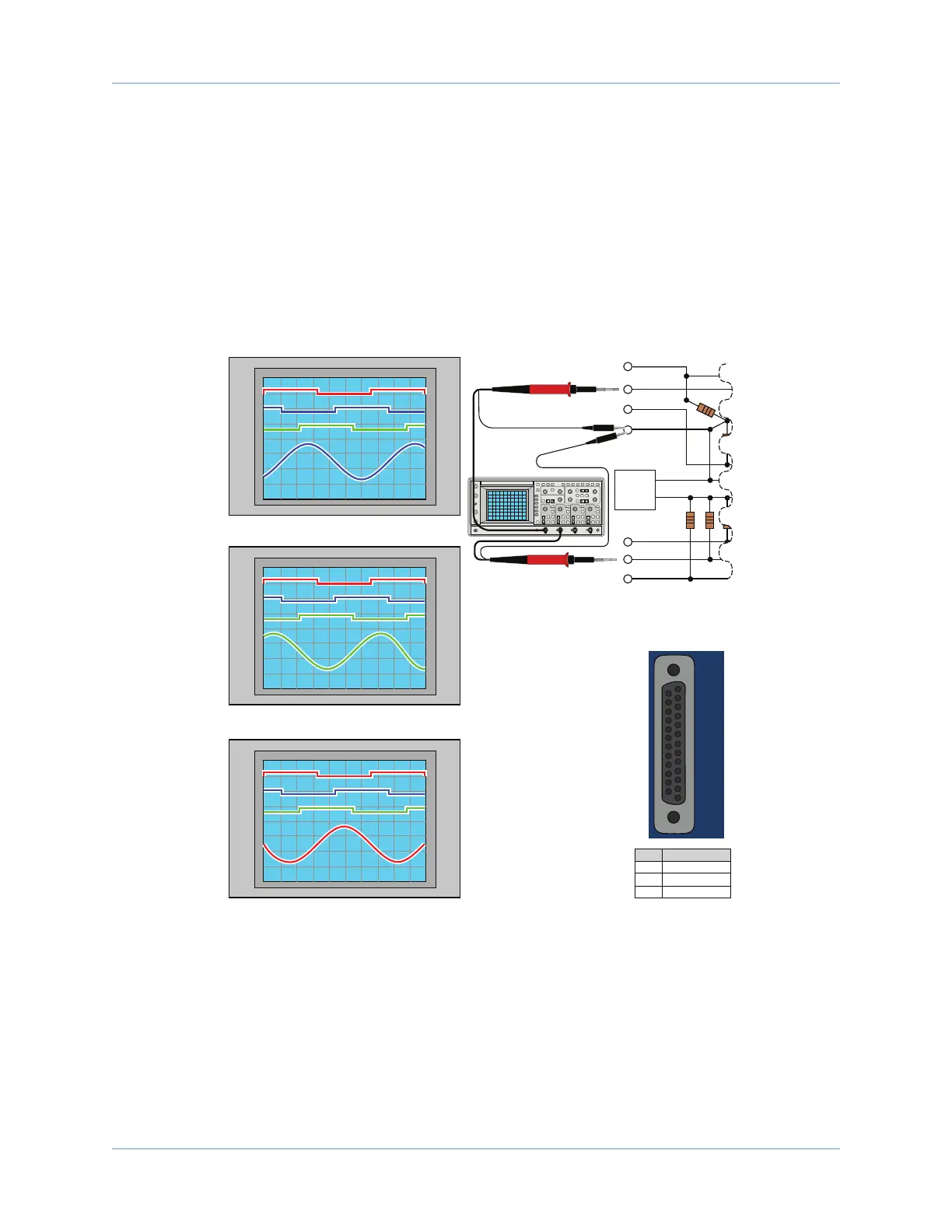
After the motor leads have been tested, the next step is to determine the phase of the Hall signals. The
required (by an Aerotech system) relationship between motor and Hall leads is that the peak of a motor lead
signal should correspond to the low voltage phase of the Hall signal (the relationship is shown in Figure 2-8).
With channel 1 still connected to one of the motor leads, connect channel 2 of the oscilloscope to TP5, TP6,
and then TP7, while advancing the motor in the positive direction after each connection. Note which of the
three Hall signals has the complimentary phase relationship to the motor lead that channel 1 is connected to
(as shown in Figure 2-8).
Move channel 1 of the oscilloscope to the second motor lead and repeat the steps from above. Note which
Hall signal corresponds to the currently selected motor lead and repeat the process for the 3rd motor lead.
TP5
TP4
COM
+5V
Power Supply
TP3
TP2
TP1
TP6
TP7
CHANNEL 1
CHANNEL 2
Channel 1 at TP1 and Channel 2 at TP5, TP6, and TP7
Channel 1 at TP2 and Channel 2 at TP5, TP6, and TP7
Channel 1 at TP3 and Channel 2 at TP5, TP6, and TP7
TP1
(CH1)
TP5
(CH2)
TP6
(CH2)
TP7
(CH2)
TP2
(CH1)
TP5
(CH2)
TP6
(CH2)
TP7
(CH2)
TP3
(CH1)
TP5
(CH2)
TP6
(CH2)
TP7
(CH2)
ØA
ØC
ØB
Hall
B
Hall
C
Hall
A
In this example:
The low voltage phase of the TP6 Hall signal corresponds
with the peak phase of the motor sine wave of TP1 (in the
previous example designated as ØB). The signal at TP6
should be designated as Hall B.
The low voltage phase of the TP7 Hall
signal corresponds with the peak phase
of the motor sine wave of TP2 (in the
previous example designated as ØC).
The signal at TP7 should be designated
as Hall C.
The low voltage phase of the TP5 Hall
signal corresponds with the peak phase
of the motor sine wave of TP3 (in the
previous example designated as ØA).
The signal at TP5 should be designated
as Hall A.
After the phasing process is complete,
the Hall A, Hall B, and Hall C signal
leads should be connected to their
respective Motor Feedback
connector inputs (Hall A to Pin 10,
Hall B to Pin 5, and Hall C to Pin 11).
Pin
10
5
11
Hall A
Hall B
Hall C
Hall Positions
Motor Feedback
Hall Pin Assignemt
5
10
11
Hall A
Hall C
Hall B
Figure 2-8: Hall Phasing with Oscilloscope
26 Chapter 2 www.aerotech.com