Installation and Configuration Ensemble Epaq Hardware Manual
With the designations of the motor and Hall leads of a third party motor determined, the motor can now be
connected to an Aerotech system. Connect motor lead A to motor connector A, motor lead B to motor
connector B, and motor lead C to motor connector C. Connect Hall lead A to Pin 10 of the feedback
connector. Hall lead B should connected to Pin 5 and Hall lead C should connect to Pin 11 of the feedback
connector.
Motor Connector
ØA
ØB
ØC
Corresponding Motor Lead
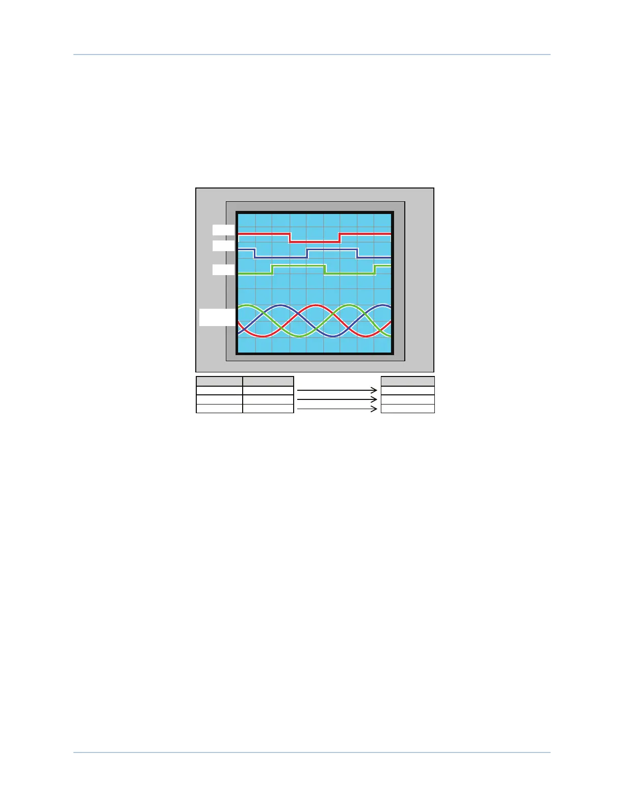
The motor is correctly phased when the Hall states correspond to the
states at each of the electrical angles. The Hall signal leads must be
associated with its corresponding motor leads.
Feedback Pins
10
5
11
Hall A
Hall B
Hall C
Hall Positions
240° 300° 360°120° 180°60°0°
5 63 421
ØAØBØC ØBØC
+V
+5V
0V
0V
-V
Hall A
Hall B
Motor Back
EMF
Hall C
Figure 2-9: Brushless Motor Phasing Goal
www.aerotech.com Chapter 2 27