© Agilent Technologies 1989–2002 Agilent 3070 / 79000 Site Preparation 6-6
Chapter 6: Site Preparation – Power Requirements: Power Requirements
Calculating the Minimum Voltage
The voltage at the testhead must be at least 90 percent of
nominal. To calculate the minimum rms voltage
multiply the rms voltage by 0.9. To calculate the
minimum peak voltage, multiply the rms voltage by 0.9
and then 1.414. For example:
208 volts rms * 0.9 = 187 volts rms
208 volts rms * 0.9 * 1.414 = 265 volts peak
See Sizing the Input Wires and Circuit Breakers
below.
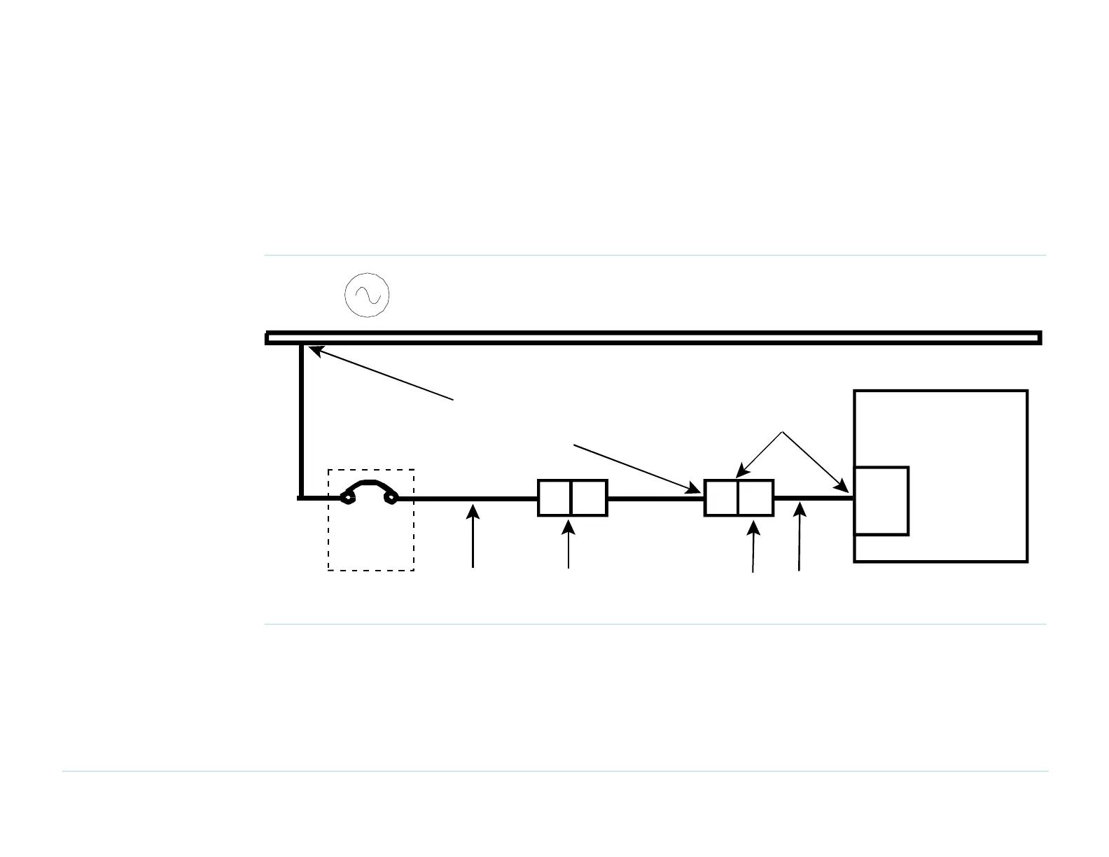
Figure 6-3 Wiring diagram
Sizing the Input Wires and Circuit Breakers
Table 6-1 on page 6-7 shows the full-load amps (FLA)
for each system type. FLA was calculated as follows:
■ For the 3X7X: a fully-loaded system with 3 STC
cards in every module.
■ For the 79000: a fully-loaded system with 6 STC
cards in the module.
3070 / 79000 System
Circuit
Breaker
or Fuses
Pigtail+.wpg
PDU
AC voltage source
Power receptacle and
power cord from the PDU
Electrician
must determine
the conductor size
Customer-installed power
drop and receptacle
Mains
Disconnect
Voltage measured at the power
receptacle or PDU, with the
system on, must be
+6%, -10% of nominal.

 Loading...


